Photocatalytic oxidation-membrane separation circulating fluid bed reaction device

A photocatalytic oxidation and circulating fluidized bed technology, which is applied in oxidation water/sewage treatment, chemical instruments and methods, chemical/physical processes, etc., can solve the problems of difficult catalyst replacement, membrane peeling, and low reactor processing capacity. Achieve high mass transfer efficiency and light energy utilization, increase reaction speed, and reduce membrane fouling

Inactive Publication Date: 2010-11-03
TIANJIN POLYTECHNIC UNIV
View PDF1 Cites 27 Cited by
  • Summary
  • Abstract
  • Description
  • Claims
  • Application Information

AI Technical Summary

Problems solved by technology

Its biggest feature is that it does not need to separate the catalyst, but the mass transfer is limited and the reactor processing capacity is small
[0006] (3) Packed bed photocatalytic reaction device: This type of reaction device is usually filled with titanium dioxide particles or silica gel, alumina, quartz sand and glass beads coated with a titanium dioxide film on the surface of the reaction device, which can effectively allow light to pass through, and With a high specific surface area, the reaction is not limited by mass transfer, but the disadvantage is that the collision between particles may cause the film to fall off, the utilization rate of light is low, and the replacement of the catalyst is very difficult
The reactor has the advantages of fast photocatalytic oxidation reaction speed and easy industrialization and application; however, due to the small volume of the photocatalytic oxidation reaction zone in the reactor, the processing capacity of the reactor is limited to a certain extent.

Method used


Image

  • Photocatalytic oxidation-membrane separation circulating fluid bed reaction device
  • Photocatalytic oxidation-membrane separation circulating fluid bed reaction device
  • Photocatalytic oxidation-membrane separation circulating fluid bed reaction device

Examples


Embodiment Construction

[0020] The present invention will be described in detail below with reference to the drawings and specific embodiments.

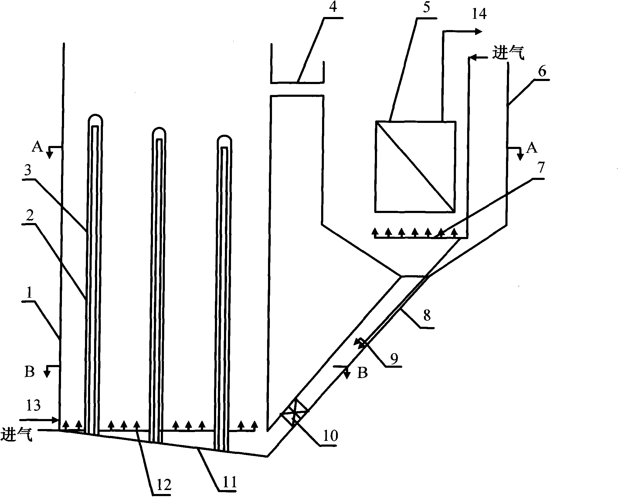
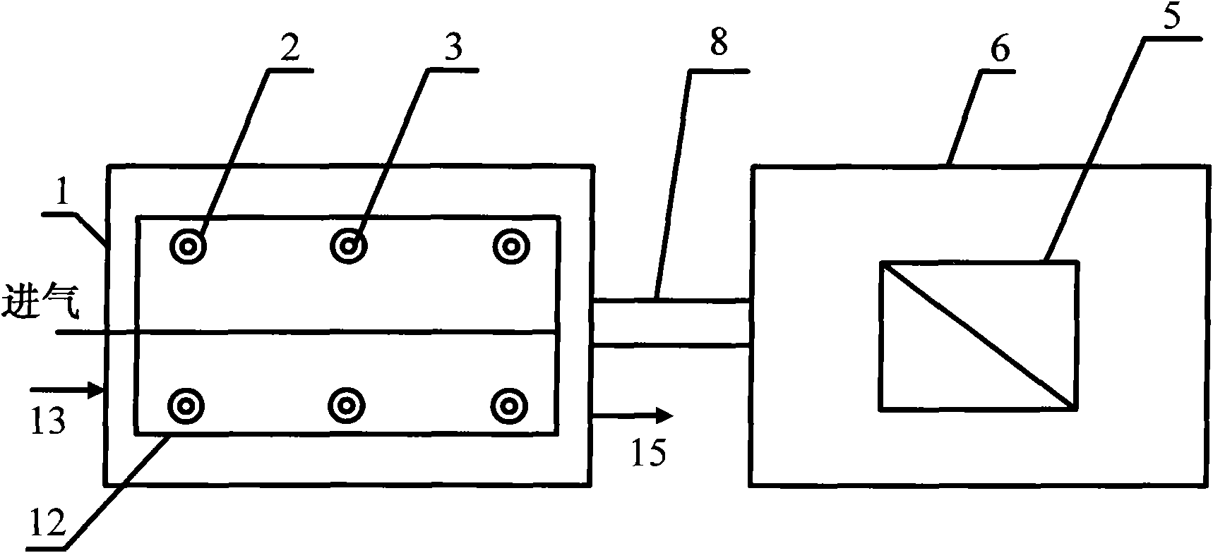
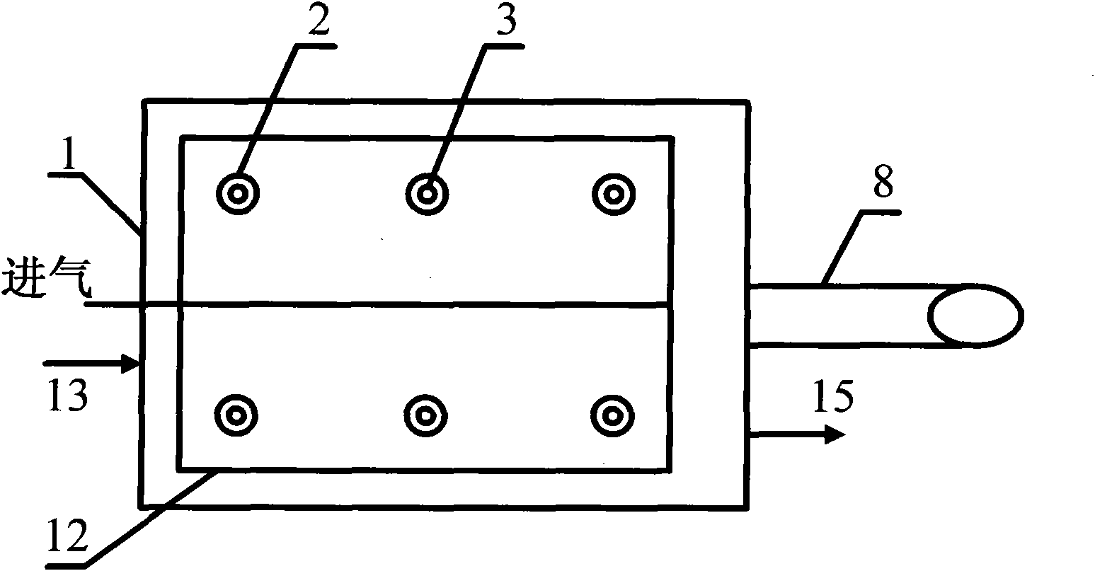
[0021] As shown in the drawings, the photocatalytic oxidation-membrane separation circulating fluidized bed reactor of the present invention includes a photocatalytic reactor 1 and a membrane separation circulating reactor 6, and the photocatalytic reactor includes a photocatalytic reactor shell , The membrane separation circulating reactor includes a membrane separation circulating reactor shell arranged on the upper side of the photocatalytic reactor shell, a plurality of ultraviolet light sources are arranged in the photocatalytic reactor shell, and The immersed membrane module 5 is arranged in the shell of the membrane separation circulating reactor, and the immersed membrane module is connected to the water outlet 14, and the lower part of the photocatalytic reactor shell is provided with a water inlet 13 and a mud drain respectively. Port 15, the upper p...


PUM


Abstract

The invention discloses a photocatalytic oxidation-membrane separation circulating fluid bed reaction device comprising a photocatalytic reactor and a membrane separation circulating reactor, wherein the photocatalytic reactor comprises a photocatalytic reactor shell; the membrane separation circulating reactor comprises a membrane separation circulating reactor shell arranged on the upper part of the side of the photocatalytic reactor shell; the photocatalytic reactor shell is internally provided with an ultraviolet light source; the membrane separation circulating reactor shell is internally provided with an immersed membrane assembly; the immersed membrane assembly is connected with a water outlet; the lower part of the photocatalytic reactor shell is respectively provided with a water inlet and a sludge discharge opening; the upper parts and the bottoms of the photocatalytic reactor shell and the membrane separation circulating reactor shell are respectively communicated through a connecting pipe and a circulating pipe; and the lower part of the photocatalytic reactor shell and the lower part of the immersed membrane assembly inside the membrane separation circulating reactor shell are respectively provided with a first aerating device and a second aerating device. The invention has higher mass transfer efficiency and light energy utilization ratio by adopting the photocatalytic oxidation-membrane separation circulating fluid bed reaction device and greatly enhances the efficiency of photocatalytic oxidation reaction.

Description

Technical field [0001] The invention relates to a reaction device, in particular to an integrated photocatalytic oxidation-membrane separation reaction device. Background technique [0002] Photocatalytic oxidation technology has become an effective method for the treatment of refractory wastewater due to its strong oxidizing ability, low secondary pollution and simple operation. Among them, TiO2 photocatalysis technology has been studied and applied more; while TiO2 photocatalysis technology faces One of the main problems is to develop a new type of integrated photocatalytic reactor and optimize the design of the developed reactor based on the research of mechanism and actual catalytic oxidation kinetics of wastewater. Therefore, the development of high-efficiency and multifunctional integrated practical photocatalytic reactors will promote the application of TiO2 photocatalytic technology in the field of wastewater treatment, especially in the treatment of refractory organic wa...

Claims


Application Information

Patent Timeline
Patent Type & Authority Applications(China)
IPC IPC(8): B01J8/22C02F1/00C02F1/32C02F1/44C02F1/74
Inventor 解立平刘艳
Owner TIANJIN POLYTECHNIC UNIV
Why Eureka
Try Eureka