Eureka AIR delivers breakthrough ideas for toughest innovation challenges, trusted by R&D personnel around the world.

Process for processing smoke

A flue gas treatment and process technology, applied in the field of metallurgy, can solve the problems of poor flue gas treatment effect, low zinc recovery rate, and large zinc recovery flue gas treatment capacity, so as to reduce equipment investment and operating costs, and reduce the scale of equipment and equipment. Small, save the effect of investment and operation cost

Inactive Publication Date: 2010-11-24
CISDI ENG CO LTD
View PDF6 Cites 21 Cited by
  • Summary
  • Abstract
  • Description
  • Claims
  • Application Information

AI Technical Summary

Problems solved by technology

There is only one flue gas treatment system in this process. The flue gas generated in the entire rotary hearth furnace including the oxidation heating zone and the high-temperature reduction zone needs to be treated by the flue gas treatment system and zinc-containing substances are recovered. However, the flue gas in the oxidation heating zone The amount is 30-50% of the total flue gas volume of the rotary hearth furnace, while the gasification emission of zinc only accounts for 1%-5% of the total zinc gasification emission. Therefore, the flue gas treatment capacity of zinc recovery is very large. The scale of the flue gas treatment system is huge, its construction investment and production and operation costs are high, and the flue gas treatment effect is poor, and the zinc recovery rate is also low
In addition, since the gasification temperature of zinc is around 906°C, the temperature of flue gas out of the rotary hearth furnace must be higher than the gasification temperature of zinc (generally around 1000°C) to take zinc away from the flue gas, so the oxidation heating The heat taken away by the flue gas in the area is relatively large, and the heat utilization efficiency of the entire rotary hearth furnace is not high

Method used


Image

  • Process for processing smoke
  • Process for processing smoke

Examples


Embodiment 1

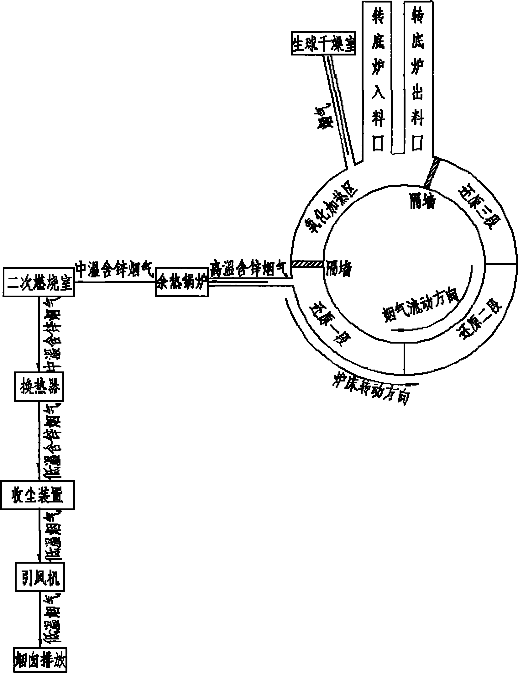
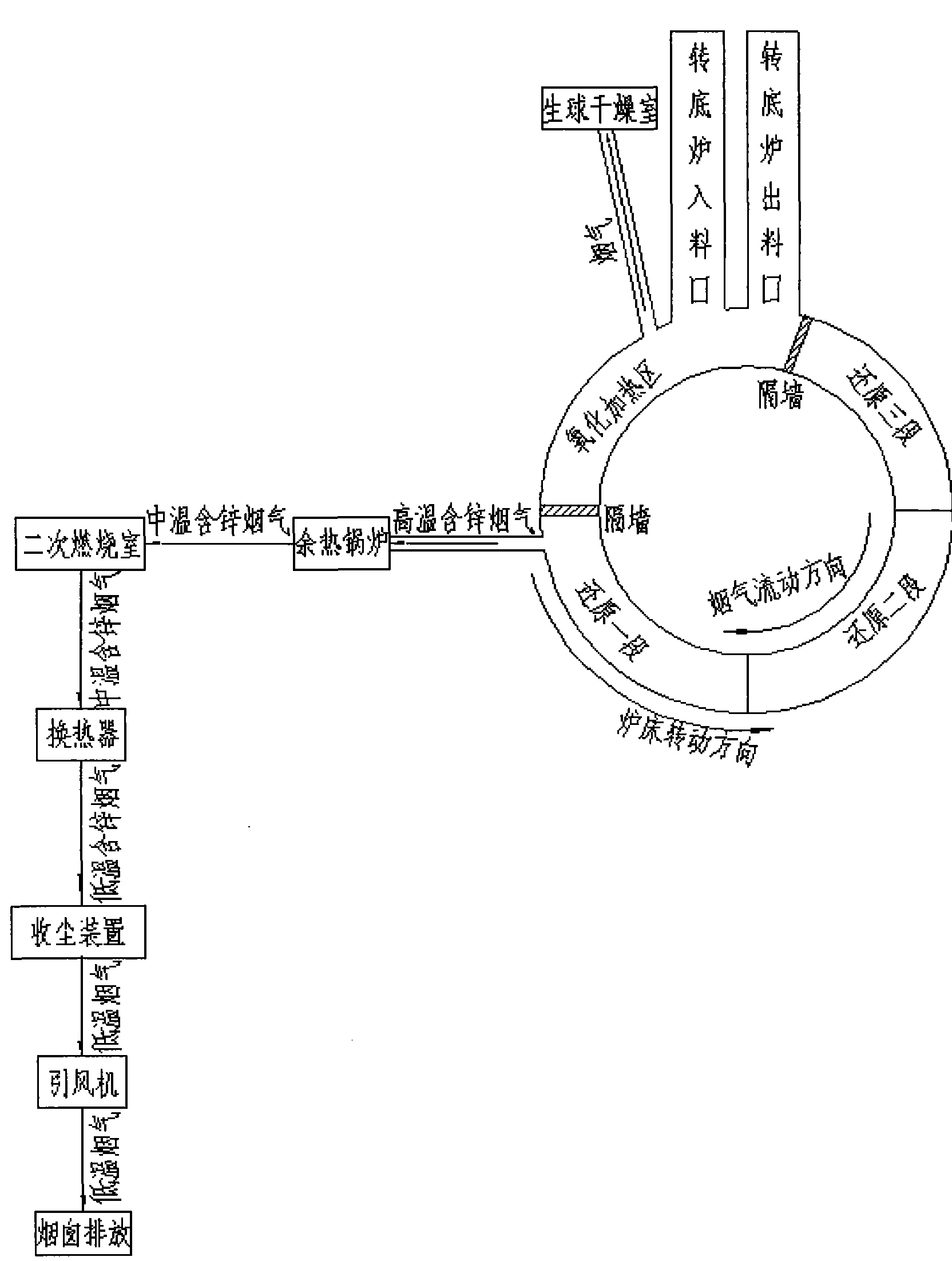
[0020] Embodiment 1, a kind of flue gas treatment process, this process carries out the staged treatment of the flue gas produced by the rotary hearth furnace;

[0021] The atmosphere in the oxidation heating zone is oxidative, the oxygen content in the flue gas is controlled at 2%, and the temperature is 800°C to 900°C. The flue gas volume in this area accounts for 35% of the total flue gas volume, and the gasification emission of zinc accounts for the total 2% of zinc gasification emissions. The main function of this area is to heat the green pellets to increase the temperature;

[0022] The flue gas in the oxidation heating zone is sent to the green pellet drying chamber in front of the rotary hearth furnace process to dry and preheat the green pellets;

[0023] The flue gas in the high-temperature reduction zone is reductive. The flue gas mainly contains incompletely combusted CO. The temperature of the flue gas is between 950°C and 1350°C. The gas volume accounts for 65...


PUM


Abstract

The invention relates to a process for processing smoke, which is characterized in that: in the process, the smoke generated by a rotary hearth furnace is subjected to segmental processing. In the process for processing the smoke, the segmental processing is performed on the smoke generated by the rotary hearth furnace, and the low zinc content smoke in an oxidation heating region is used for drying a preheated green ball, so the waste heat of the smoke can be completely recycled, unburned gas can also be combusted completely to recycle usable waste heat further; the smoke in a high-temperature reducing region where the zinc is gasified and volatilized intensively is subjected to dust removal and zinc recycling after waste heat recycling and secondary combustion, and the amount of the smoke which needs to perform zinc recycling is reduced, so the equipment investment and operation cost of a smoke processing system are reduced; and due to the secondary waste heat recycling and the secondary combustion of the smoke in the high-temperature reducing region, the waste heat of the smoke in the region can be completely recycled, the recovery rate of the zinc is improved, and the environmental pollution is reduced.

Description

technical field [0001] The invention belongs to the technical field of metallurgy, and relates to a direct reduction process of zinc-containing dust and sludge in iron and steel metallurgy, in particular to a flue gas treatment process using coal or coke powder as a reducing agent and adopting a rotary hearth furnace to directly reduce zinc-containing dust and sludge. Background technique [0002] At present, domestic and foreign rotary hearth furnaces for treating zinc-containing dust and sludge in iron and steel enterprises mainly include the fastmelt process jointly developed by Japan's Kobe Steel and the Midland Company of the United States, and the Inmetco process developed by Canada's International Nickel Corporation. Their process is similar. First, the raw materials including iron and steel plant dust, coal powder, binder, etc. are mixed through a mixer, and then pelletized by a pelletizer and dried to preheat the raw pellets, and then enter the rotary hearth furnace....

Claims


Application Information

Patent Timeline
Patent Type & Authority Applications(China)
IPC IPC(8): F27D17/00
CPCY02P10/25Y02P80/15
Inventor 胡斐印民雍海泉郭秀键
Owner CISDI ENG CO LTD
Why Eureka
Eureka Blog
Learn More