Device and method for continuously analyzing single-cell contents by miniflow control chip at high speed

A microfluidic chip and content technology, applied in the field of single-cell analysis, can solve problems such as not being widely used, and achieve the effects of increasing the injection rate, reducing the concentration, and having a simple structure

Inactive Publication Date: 2010-12-22
HANGZHOU NORMAL UNIVERSITY
View PDF3 Cites 23 Cited by
  • Summary
  • Abstract
  • Description
  • Claims
  • Application Information

AI Technical Summary

Problems solved by technology

For these reasons, methods for continuous high-speed analysis of substan

Method used


Image

  • Device and method for continuously analyzing single-cell contents by miniflow control chip at high speed
  • Device and method for continuously analyzing single-cell contents by miniflow control chip at high speed
  • Device and method for continuously analyzing single-cell contents by miniflow control chip at high speed

Examples


Embodiment 1

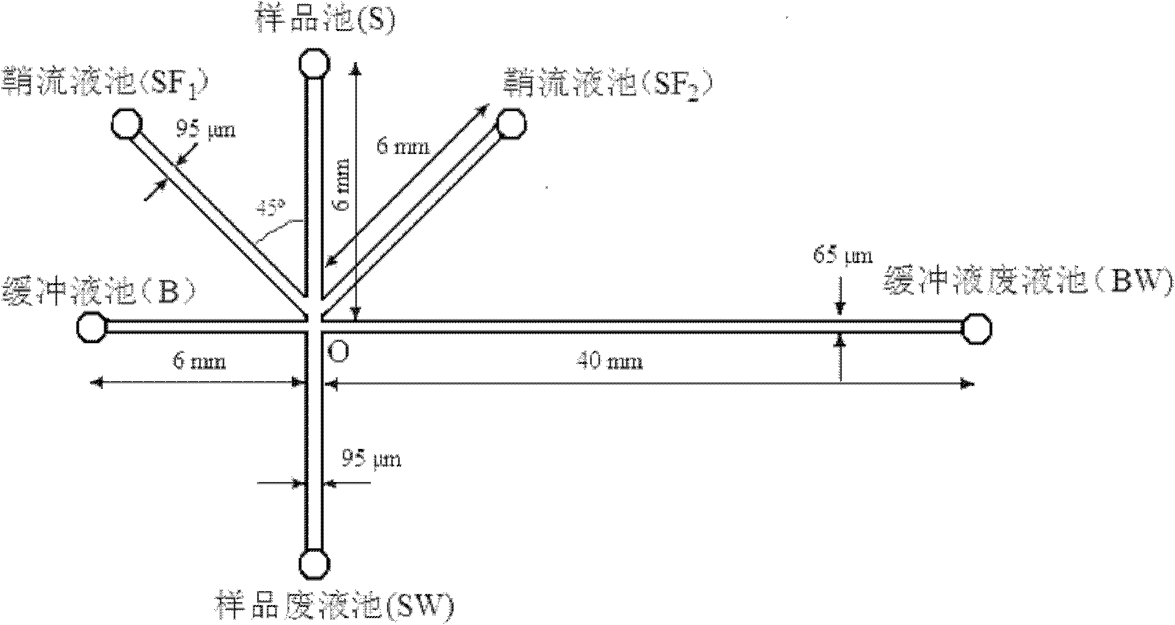
[0022] see figure 1 , the microfluidic chip has a buffer pool (B), a sample pool (S), a sample waste pool (SW), two sheath flow pools (SF 1 and SF 2 ) and buffer waste reservoir (BW). The sampling channel is S-SW, the length is 12 mm, the channel width is 95 μm, the depth is 35 μm, the length of channel S-O is 6 mm; the separation channel is B-BW, the length is 46 mm, the channel width is 65 μm, the depth is 20 μm, and the length of channel B-O is 6 mm; The sample channel crosses the separation channel at point O. There is a sheath flow channel on both sides of the sampling channel, which intersects with the sampling channel at 200nm above point O. The sheath flow channel is 95 μm wide, 35 μm deep, and 6 mm long. A small hole is punched at the end points of the sampling channel, the separation channel and the sheath flow channel, and the micro plastic liquid reservoir is glued on the small hole with an adhesive.

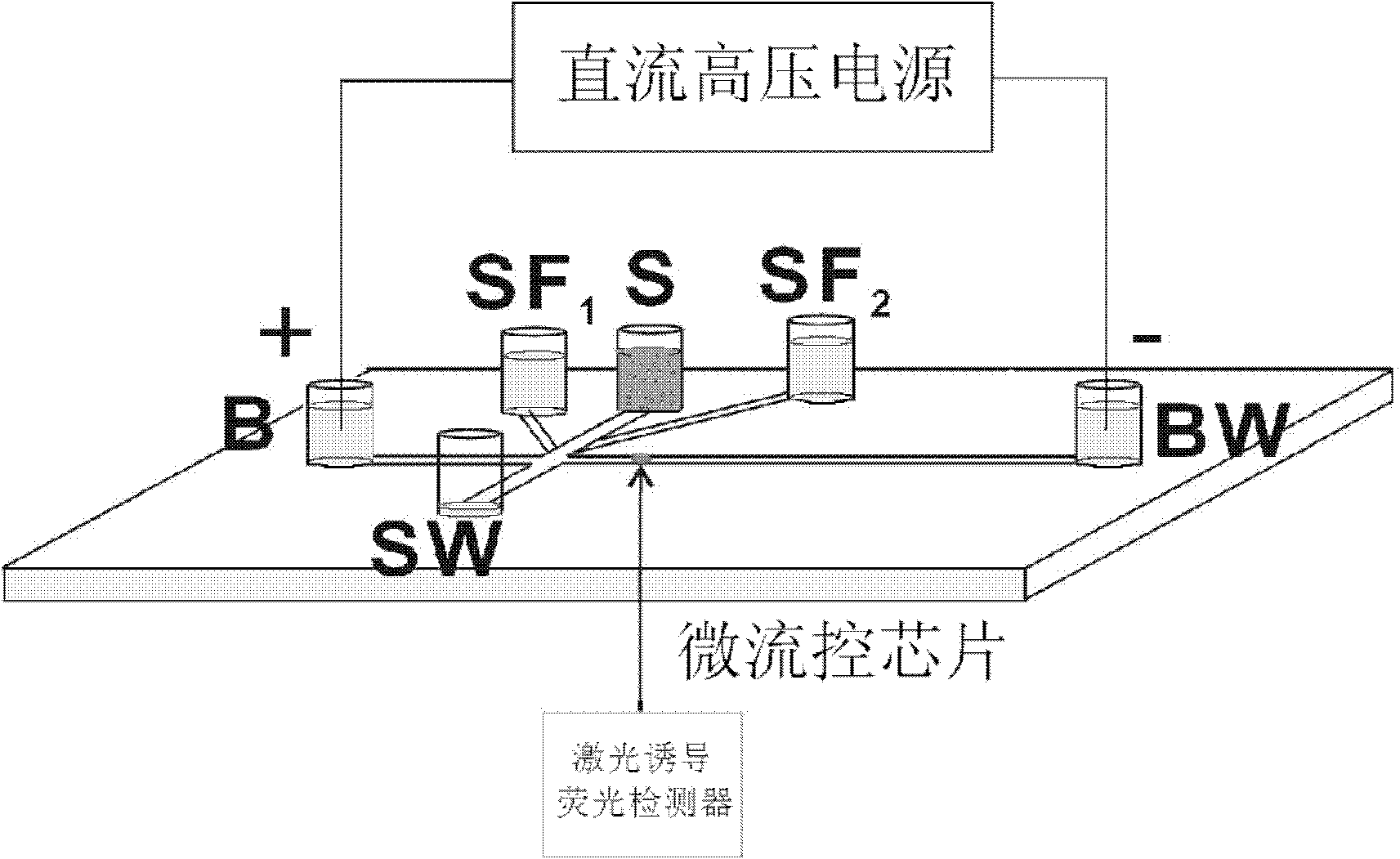
[0023] see figure 2 Add 100 μL and 100 μL of electrophore...

Embodiment 2

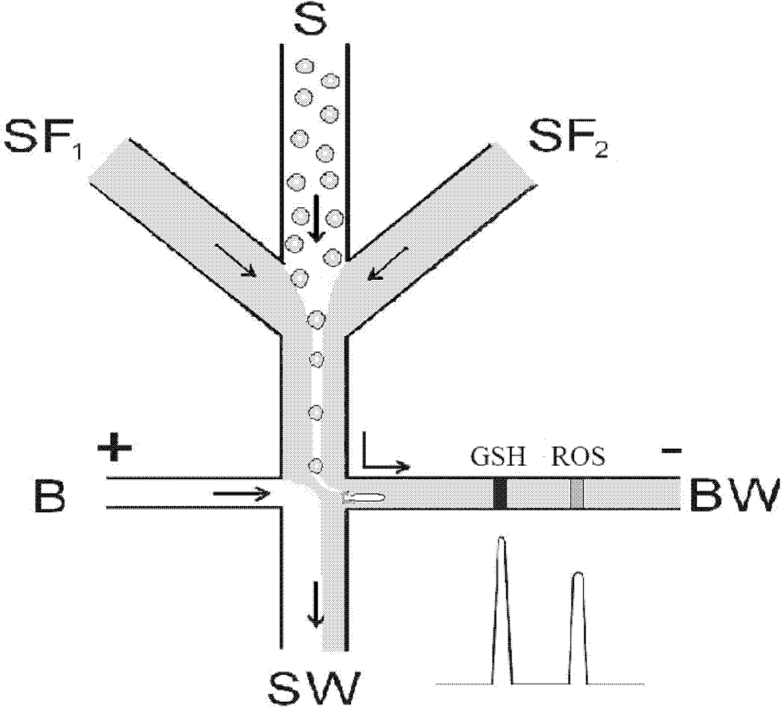
[0025] Example 2: Determination of glutathione and reactive oxygen species in a single red blood cell

[0026] The microfluidic chip used in this example is consistent with Example 1, and the sample is red blood cell suspension. Label glutathione and reactive oxygen species in cells with naphthalene dicarbaldehyde and dihydrorhodamine 123, respectively, and dilute with normal saline to prepare a density of 1.2×10 5 After the cells / mL cell suspension was added to the sample pool; 20mmol boric acid buffer solution (pH 9.2) was added to the reservoirs B and BW, and the electrophoresis buffer containing the film dissolving agent (tritonX-100, concentration 1%, w / w) solution (20mmol boric acid buffer solution, pH 9.2) into the sheath flow reservoir SF 1 and SF 2 In, the amount of liquid added in each reservoir is consistent with that of Example 1. Apply a 2000V DC voltage to the B and BW reservoirs at the two ends of the separation channel.

[0027] Cells in the erythrocyte sus...


PUM


Abstract

The invention provides a miniflow control chip which has a simple structure and can continuously analyzing single-cell contents at high speed and an operation method. The invention is characterized in that a sheath flow passageway is arranged at each side of a sample injection passageway of a cross-miniflow control chip; through adjusting static pressure difference between liquid storage tanks, cell suspension and sheath flow liquid simultaneously flow out of a sample reservoir and a sheath flow liquid reservoir; under the action of sheath flow, single cells in the cell suspension rank in a row to enter into a separation passageway from the sample injection passageway in turn, contact with a film dissolving agent in the process of movement and conduct rapid film dissolution at the inlet of the separation passageway; the film-dissolved cell contents fully enter into the separation passageway to be continuously separated at high speed under the action of an field stress generated at two ends of the separation passageway; and laser induces fluorescence detection. As the solution entering into the separation passageway is a mixed solution of the sheath flow liquid and normal saline in the cell suspension, the invention can also greatly reduce the concentration of the normal saline entering into the separation passageway and markedly lower band broadening caused by Joule heat when electrophoresis is carried out.

Description

(1) Technical field [0001] The invention relates to a device and method for continuously and high-speed analysis of substances in a single cell by using a microfluidic chip, and belongs to the technical field of single cell analysis. (2) Background technology [0002] Single-cell analysis is of great significance to the early diagnosis, treatment, drug screening, and research on cell physiology and pathological processes of major diseases such as cancer. Due to the small size of the cells (diameter 8 μm-200 μm, volume fL-nL), the sample volume is very small (zmol-fmol), and the intracellular components are very complex, so the analysis is very difficult. Capillary electrophoresis is currently the most widely used method for single-cell multicomponent analysis. However, the capillary electrophoresis technology is limited by the one-dimensional structure of the capillary. When a single cell enters the capillary electrophoresis, it needs to use a micron-sized tip drawn from a ...

Claims


Application Information

Patent Timeline
IPC IPC(8): G01N21/64C12Q1/02
Inventor 殷学锋徐春秀刘金华
Owner HANGZHOU NORMAL UNIVERSITY
Why Eureka
Try Eureka