Electric field strengthening two-phase anaerobic reactor

An anaerobic reactor and electric field technology, applied in anaerobic digestion treatment, waste fuel, etc., can solve problems such as poor removal of sulfate wastewater, reduced residence time in the acidification stage, and uneven distribution of current, so as to speed up Effects of reduction rate, reduction of substrate competitive inhibition, and acceleration of reproduction rate

Inactive Publication Date: 2010-12-29
NANJING UNIV
View PDF5 Cites 10 Cited by
  • Summary
  • Abstract
  • Description
  • Claims
  • Application Information

AI Technical Summary

Problems solved by technology

[0006] The Chinese patent "An electric field reaction device" (publication number CN201244477Y) adopts two poles of the electric field distributed on both side walls of the reactor, and the electrodes are composed of a single electrode or a combination of multiple plates. Such plate distribution makes the reaction The current in the area cannot be evenly distributed, which affects the treatment effect
However, H 2 The concentration of S is still high, and the problem of matrix competition has not been solved. The acceleration of hydraulic upflow velocity will lead to the decrease of residence time in the acidification stage, and the high-load sulfate wastewater will not be well removed, and related studies have shown that the use of hydrogen The sulfate-reducing bacteria of SRB still need a long reduction rate for the most easily available substrate - hydrogen, let alone other types of SRB

Method used


Image

  • Electric field strengthening two-phase anaerobic reactor
  • Electric field strengthening two-phase anaerobic reactor
  • Electric field strengthening two-phase anaerobic reactor

Examples


Embodiment Construction

[0023] In order to further illustrate the present invention, the specific embodiments of the present invention will be described in detail below.

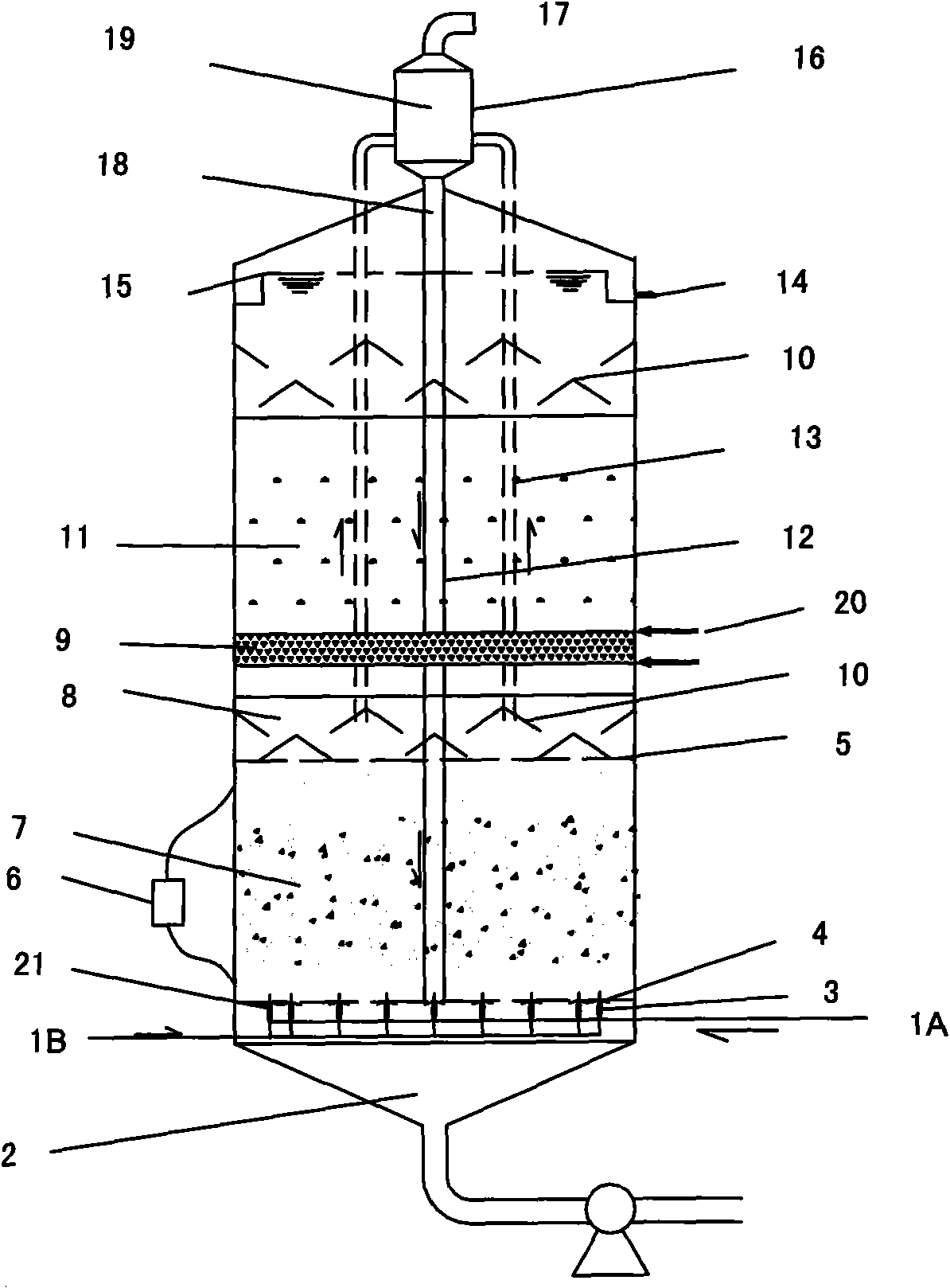
[0024] Such as figure 1 , the electric field enhanced two-phase anaerobic reactor of the present invention, its tank body structure is vertical cylinder or cuboid, by the sludge sedimentation area 2 in the tank body, acidification reaction chamber 7, methanation reaction chamber 22 and the gas at the upper end of the tank body The liquid separator 19 is composed.

[0025]The bottom of the tank is connected with a sludge output pipe, and the sludge output pipe is connected with the sludge sedimentation area 2; the top of the tank is provided with a gas-liquid separator 19, and the lower part of the gas-liquid separator 19 is provided with a return pipe 18, and the return pipe 18 extends into the tank and connected to the water distributor 3 located at the bottom of the acidification reaction chamber 7, the position of the water dis...


PUM


Abstract

The invention discloses an electric field strengthening two-phase anaerobic reactor being suitable for treating high-concentration sulfates and organic pollutant effluents. The interior of a tank body of the reactor is respectively provided with a sludge precipitation zone, an acidification reaction chamber and a methanation reaction chamber from the bottom up; the top of the tank body is provided with a gas-liquid separator; the upper side and the lower side of the acidification reaction chamber are respectively provided with a negative electrode plate and a positive electrode plate, and the negative electrode plate and the positive electrode plate are connected with a constant-current voltage source outside the tank body so as to form a constant-voltage electric field; the methanation reaction chamber and the acidification reaction chamber are separated by a sludge trapping layer; the inner edge at the top of the tank body is provided with a water outlet slot; a water outlet pipe is communicated with the water outlet slot and extends out of the tank body, and the effluent thereof can be directly discharged or recycled. The processes of the constant-voltage electric filed and the two-phase anaerobic reactor are adopted in the reactor; and the reactor adopts a sulfate reduction process which can realize that a hydrogen supply system is strengthened at constant pressure under the condition of introducing direct current. The reactor has the advantages of high volume load, high reaction speed, small occupied area, low operating cost, good treatment effect, and the like.

Description

technical field [0001] The invention relates to an anaerobic organic sewage biological treatment integrated device with an external constant voltage electric field, which is used for treating organic polluted waste water containing high-concentration sulfate, specifically an electric field-strengthened two-phase anaerobic reactor. technical background [0002] With the rapid development of human society in recent centuries, a large amount of production and domestic sewage has been discharged, seriously affecting the quality of human life; especially since the industrial revolution in the 19th century, chemical, pharmaceutical, tanning, papermaking, fermentation While a large amount of organic pollutants are discharged in the production process of food processing, mining and other fields, high-concentration sulfate wastewater is also generated. High-concentration sulfate organic wastewater has seriously damaged various ecological environments. The sulfate wastewater will acid...

Claims


Application Information

Patent Timeline
Patent Type & Authority Applications(China)
IPC IPC(8): C02F3/28
CPCY02E50/30
Inventor 刘波姜国兴吴文菲屈晋云王艳鹏戚绪亮李松
Owner NANJING UNIV
Why Eureka
Try Eureka