Tunable dual-frequency laser

A dual-frequency laser and laser cavity technology, applied in the field of lasers, can solve problems such as instability, poor stability, and needs, and achieve the effect of stable work and small system size

Active Publication Date: 2011-04-13
FUZHOU PHOTOP QPTICS CO LTD
View PDF4 Cites 4 Cited by
  • Summary
  • Abstract
  • Description
  • Claims
  • Application Information

AI Technical Summary

Problems solved by technology

[0003] The technical solution of U.S. Patent No. 3,453,557 proposes a dual-frequency laser system, which adopts the laser system of power balance method frequency stabilization technology, and alternately transmits the up-shifted optical frequency component and the down-shifted optical frequency component through the liquid crystal optical switch element The disadvantages of this system are: (1) The output laser light frequency is not tunable; (2) A liquid crystal switching element is required. When there is a lack of liquid crystal switching elements, a solid crystal optical switch needs to be used instead , which requires a high-voltage power supply, and it is difficult to integrate the whole system
The disadvantages of this system are: (1) poor stability of the external cavity structure; (2) high voltage power supply and piezoelectric ceramic components are required; (3) methane is a volatile liquid
The disadvantages of this system are: (1) poor stability; (2) too many reflective surfaces, difficult to adjust, and large loss
The disadvantages of this system are: 1) The pump light energy of the two wavelengths is inconsistent, and the output energy of the two wavelengths will be different; 2) The output light of the two wavelengths is coaxial and cannot be separated; 3) The laser is unstable

Method used


Image

  • Tunable dual-frequency laser
  • Tunable dual-frequency laser
  • Tunable dual-frequency laser

Examples


Embodiment 1

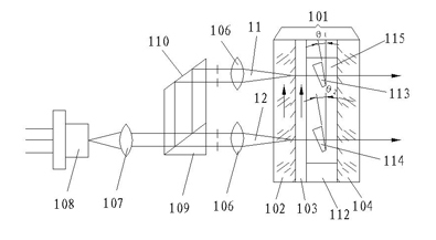
[0025] Embodiment 1: A non-polarizing beam splitter is used to split the pump light emitted by the same semiconductor light source into two beams of approximately equal power, the same polarization, and spaced apart.

[0026] Such as figure 1 As shown, 101 is a microchip single longitudinal mode laser cavity, 102 is a front cavity lens, 104 is a rear cavity lens, 103 is an ultra-thin laser gain medium sheet, such as Nd: YVO4, 111 and 112 are etalon support frames, 113 and 114 are the first optical parallel flat plate and the second optical parallel flat plate of the ultra-thin optical parallel flat plate, and the laser cavity at the two pumping points can be fine-tuned by fine-tuning the angles of the first optical parallel flat plate 113 and the second optical parallel flat plate 114 Long, so that the frequency difference of the microchip laser can be adjusted. 106 and 107 are optical lenses, which respectively act as coupling pump beams and collimating pump beams; 108 is a ...

Embodiment 2

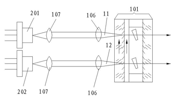
[0027] Embodiment 2: Two semiconductor light sources of the same type are used to pump separately, so that the polarization directions of the pump light emitted by the semiconductor light sources are consistent.

[0028] Such as figure 2 As shown, 201 and 202 are two semiconductor light sources of the same type spaced apart from each other, and the output pump light power and polarization direction are consistent. The semiconductor light sources 201 and 202 are respectively collimated by the collimator lens 107 to emit two pump beams with the same power and polarization direction, and the beam splitting ratio of the non-polarizing beam splitter 109 is 1:1.

Embodiment 3

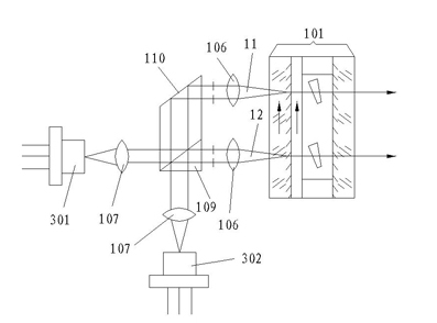
[0029] Embodiment 3: Two semiconductor light sources with the same polarization are used to simultaneously pump two points on the microchip through a non-polarizing beam splitter and a reflector.

[0030] Such as image 3 As shown, 301 and 302 are respectively two semiconductor light sources with the same polarization arranged vertically and orthogonally, and their output light powers may be inconsistent. Since the two outgoing beams are split into two parts by the non-polarizing beam splitter 109, the power of the first pumping beam 11 and the second pumping beam 12 is half of the output power of the semiconductor light source 301 plus half of the output power of the semiconductor light source 302 , so that even if the output power of the semiconductor light source is inconsistent, the pump light power is the same.

[0031] For all the above-mentioned examples, different nonlinear crystal back-end mirror coatings can be added to the laser cavity at the two pumping points on ...


PUM


Abstract

The invention relates to the field of lasers, in particular to a dual-frequency laser. In a tunable dual-frequency laser, a first pump beam and a second pump beam with the same power and polarization direction are incident into a microchip laser cavity at spatial intervals; and the microchip laser cavity at least comprises a front cavity lens, a laser gain dielectric slab, an etalon of an air gap, and a rear cavity lens which are sequentially glued, wherein the etalon of the air gap is formed by fixing the laser gain dielectric slab and the rear cavity lens by using two etalon supports at an interval, and a first optical plain film and a second optical plain film with the same thickness or almost same thickness are respectively inserted into a first optical path and a second optical path of the first pump beam and the second pump beam in the gap to respectively adjust the output wavelength of the laser. Therefore, in the dual-frequency laser wavelengths are tunable, and the laser is stable in working and has a small size.

Description

technical field [0001] The invention relates to the field of lasers, in particular to dual-frequency lasers. Background technique [0002] Research on dual-frequency lasers in communication optical fibers; image processing of satellite transmission photos; precise measurement of relative phase and displacement; research on optically active substances in light industry and chemical industry; measurement of optical components and optical film properties; precision optical measurement; precision mechanical measurement ; laser power supply for precision instruments and advanced laboratories; form a dual-frequency laser array to generate a dual-frequency frequency difference of several hundred megahertz, and other fields have a wide range of applications. [0003] The technical solution of U.S. Patent No. 3,453,557 proposes a dual-frequency laser system, which adopts the laser system of power balance method frequency stabilization technology, and alternately transmits the up-...

Claims


Application Information

Patent Timeline
Patent Type & Authority Applications(China)
IPC IPC(8): H01S3/08H01S3/0941H01S3/109
Inventor 吴砺贺坤魏豪明刘国宏陈卫民
Owner FUZHOU PHOTOP QPTICS CO LTD
Why Eureka
Try Eureka