Graphite Raman locked mode laser

A graphene and laser technology, applied in the direction of lasers, laser components, phonon exciters, etc., to achieve the effect of expanding the application range, high practical value, and wide application

Active Publication Date: 2011-06-22
SHANGHAI INST OF OPTICS & FINE MECHANICS CHINESE ACAD OF SCI
View PDF4 Cites 25 Cited by
  • Summary
  • Abstract
  • Description
  • Claims
  • Application Information

AI Technical Summary

Problems solved by technology

However, due to the limitation of the output band of the general laser gain medium and the band limitation of the saturable absorber, it is difficult to achieve ultrashort pulse output in the band where the ordinary laser gain medium and the saturable absorber cannot work [patent name: PASSIVELY MODELOCKED FIBER LASERUSING CARBON NANOTUBES , application number: EP200900012100, publication number: EP2169785], therefore, its application is limited

Method used


Image

  • Graphite Raman locked mode laser
  • Graphite Raman locked mode laser
  • Graphite Raman locked mode laser

Examples


Embodiment 1

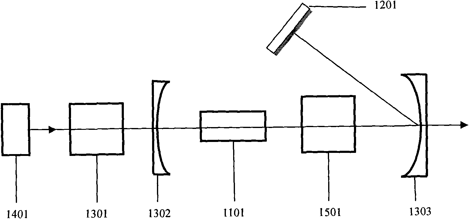
[0033] see figure 2 , figure 2 It is a structural schematic diagram of Embodiment 1 of the graphene Raman mode-locked laser of the present invention. It can be seen from the figure that the flexible wavelength mode-locked laser of the present invention includes a pump source 1401, an input coupling system 1301, a first reflector 1302, a second reflector 1303, a potassium gadolinium tungstate crystal 1101, a graphene mode-locked device 1201, Grating pair 1501. Potassium gadolinium tungstate crystal 1101 is used to provide Raman gain, graphene mode-locking device 1201 is made by placing graphene on a mirror to realize passive mode locking in the cavity, and grating pair 1501 is used to control the The dispersion is compensated to realize the compression of the mode-locked pulse, and the second mirror 1303 is used to output the intracavity oscillating light. By changing the central wavelength of the pump light, combined with the stimulated Raman scattering effect, the disper...

Embodiment 2

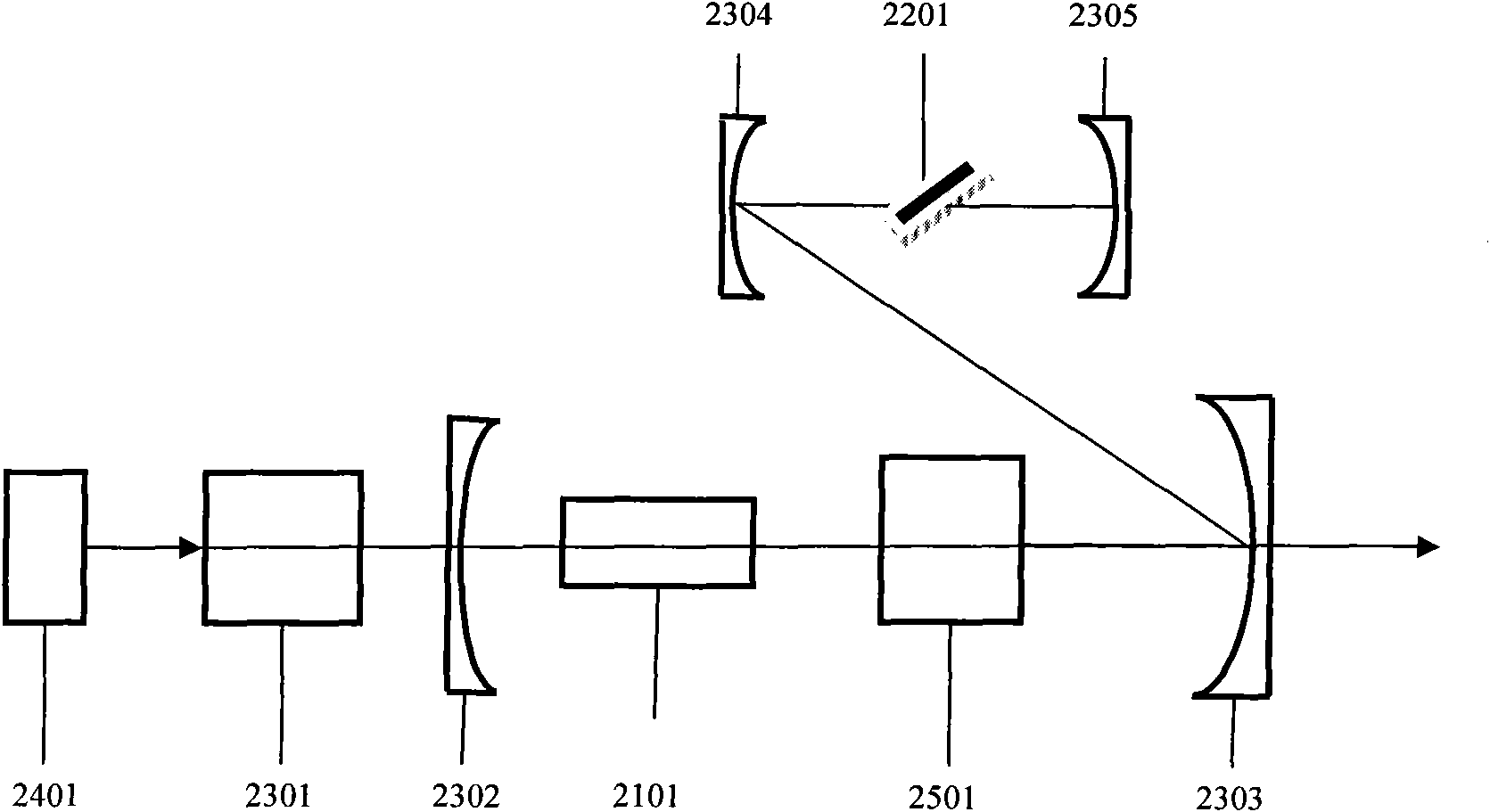
[0035] see image 3 , image 3It is a structural schematic diagram of Embodiment 2 of the present invention. It can be seen from the figure that the flexible wavelength mode-locked laser of the present invention includes a pump source 2401, an input coupling system 2301, a first mirror 2302, a potassium gadolinium tungstate crystal 2101, a graphene mode-locked device 2201, a grating pair 2501, a second Reflecting mirror 2303, third reflecting mirror 2304, and fourth reflecting mirror 2305. The pump light 2401 with different central wavelengths is input into the laser cavity through the input coupling system 2301. The potassium gadolinium tungstate crystal 2101 is used to provide Raman gain. The mode-locking device is used to achieve passive mode locking in the cavity, the grating pair 2501 is used to compensate the dispersion in the cavity to realize the compression of the mode-locked pulse, and the second mirror 2303 is used to output the oscillating light in the cavity. B...

Embodiment 3

[0037] see Figure 4 , Figure 4 It is a structural schematic diagram of Embodiment 3 of the present invention, Figure 5 , Figure 6 , Figure 7 and Figure 8 Respectively the specific form of the graphene mode-locked device in embodiment 3. Figure 5 It is a cross-sectional view of a section of single-mode optical fiber that is tapered, and then graphene is placed in the tapered area. In the figure, 5201 is the cladding of the single-mode optical fiber, 5202 is the graphene in the tapered area of ​​the optical fiber, and 5203 is the core of the optical fiber; Figure 6 It is a cross-sectional view of engraving a U-shaped groove on one side of a single-mode fiber, and then placing graphene in the U-shaped groove area; 6201 in the figure is the cladding of the single-mode fiber, and 6202 is the graphene in the U-shaped groove area , 6203 is the fiber core; Figure 7 It is to absorb graphene on the end face of the fiber by optical precipitation for a section of single-mod...


PUM


Abstract

The invention relates to a graphite Raman locked mode laser characterized in that laser gain is provided by a stimulated Raman scattering effect with a flexible wavelength and combined with a graphite Raman locked mode device with a wide saturated absorption band to realize locked mode laser output. The whole device of the graphite Raman locked mode laser is formed by a mechanism of combining a stimulated Raman gain medium with the graphite Raman locked mode device, is compact in structure and convenient to integrate and can be applied to a plurality of fields.

Description

technical field [0001] The invention relates to a mode-locked laser, in particular to a graphene Raman mode-locked laser combining the stimulated Raman scattering effect with flexible wavelength and the broad saturable absorption characteristic of graphene. Background technique [0002] Ultrashort pulse laser technology is one of the most important frontiers of modern science. In the past 30 years, scientists have gained a deep understanding of the dynamic process of chemical reactions on the femtosecond scale and the energy band relaxation process of semiconductors and solid materials, and even captured The movement process of electrons around electron nuclei that has reached attosecond relaxation. Ultrashort pulse laser technology has developed rapidly. Mechanisms such as active mode-locking, passive mode-locking, synchronous pump mode-locking, and self-mode-locking have been used in mode-locked lasers one after another, making ultrashort pulse technology a huge developmen...

Claims


Application Information

Patent Timeline
Patent Type & Authority Applications(China)
IPC IPC(8): H01S3/30H01S3/098H01S3/16H01S3/067
Inventor 张磊冯衍
Owner SHANGHAI INST OF OPTICS & FINE MECHANICS CHINESE ACAD OF SCI
Why Eureka
Try Eureka