
Method for making rectangular deep cut-off ultra-narrow band pass filter

A manufacturing method and technology of optical filters, applied in the direction of optical filters, etc., can solve problems such as unfavorable stability, transmittance change, poor cutoff, etc., achieve high practical value, reduce control errors, and improve production efficiency Effect

Inactive Publication Date: 2011-08-03
SOUTH WEST INST OF TECHN PHYSICS
View PDF0 Cites 26 Cited by
  • Summary
  • Abstract
  • Description
  • Claims
  • Application Information

AI Technical Summary

Problems solved by technology

After the spectrum of a single-cavity filter drifts with temperature, the transmittance at the working wavelength may change greatly, which is not conducive to the stability of the work
[0011] 2. Poor cut-off
Especially for the multi-cavity filter, which is a precision thin film that is extremely sensitive to control errors, a little carelessness in the coating process is very likely to affect each other between the multi-cavities, resulting in the deformation of the passband of the obtained product or even collapse and become a waste product.

Method used


Image

  • Method for making rectangular deep cut-off ultra-narrow band pass filter
  • Method for making rectangular deep cut-off ultra-narrow band pass filter
  • Method for making rectangular deep cut-off ultra-narrow band pass filter

Examples


Embodiment Construction

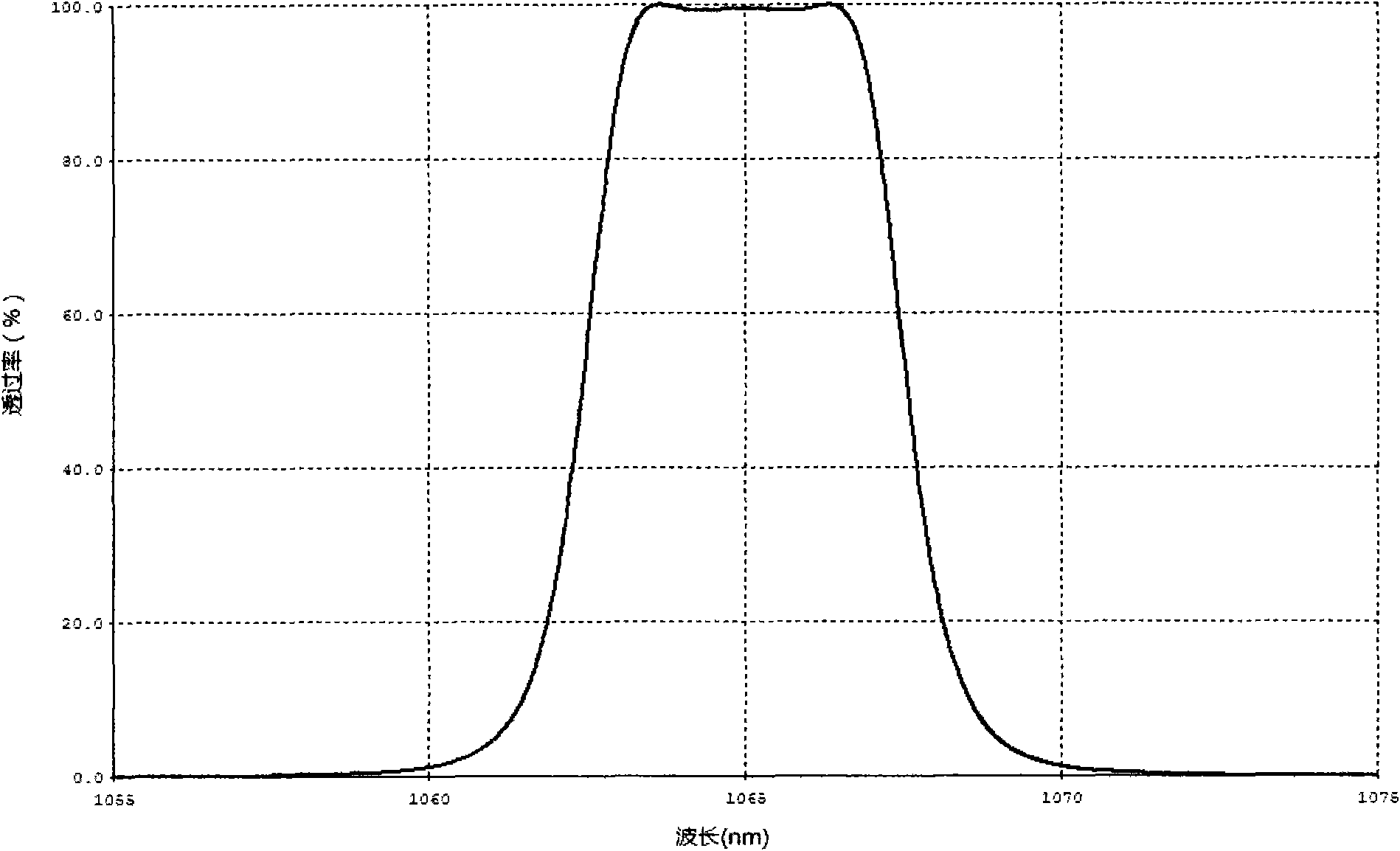
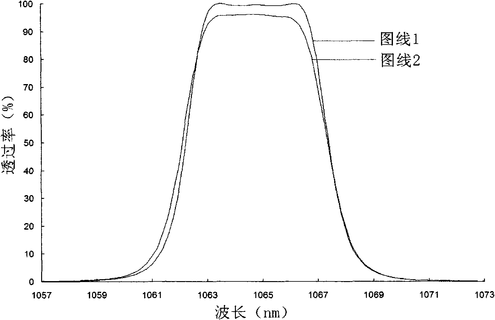
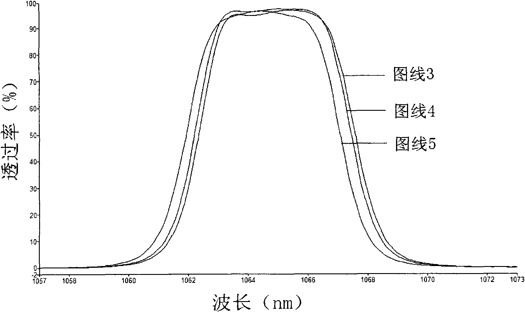
[0028] refer to figure 1 . In order to solve the shortcomings of single-cavity filters, for applications that require very strict filter performance, multi-cavity filter designs can usually be used to obtain better rectangularity and cut-off through the superposition of multiple interference cavities. degree and required passband width. According to the theoretical design curve of a rectangular deep-cut ultra-narrow bandpass filter working at 1064nm with a typical half-width of 5.2nm, firstly, determine the theoretical film system, and select Ta 2 o 5 As a high refractive index material, SiO 2 is a low refractive index material, with λ being 1064nm, respectively defining Ta 2 o 5 and SiO 2 The unit optical thicknesses at λ / 4 are H and L. The performance parameters of the optical filter include theoretical half-width, distribution value of 5-5.4nm, and the width of the region where the passband average transmittance is greater than or equal to 95%, and its width is not ...


PUM


Abstract

The invention provides a method for making deep cut-off ultra-narrow band pass filter. By adopting the method, the effective area and the cut-off of the bandpass filter can be obviously improved and error negative effects can be effectively controlled. The method comprises the following steps of: 1, determining a theoretical film, selecting Ta2O5 as a high-reflectivity material and SiO2 as a low-reflectivity material on the basis of a typical film structure of a multi-cavity optical filter, respectively defining H and L to be the unit optical thickness of the Ta2O5 and the SiO2 on lambda fourth by taking lambda as an operating wavelength of the optical filter, and determining the film structure of the optical filter by using film design software thin film circuit (TFC) Calc on a computer according to performance parameters required by the ultra-narrow band pass filter; 2, making a template control file for automatic control of a coating machine by using the full-automatic coating machine according to the obtained theoretical film structure; and 3, loading selected coating materials in the coating machine and automatically completing the making of the optical filter through a control mode of eccentric monitoring by the coating machine according to a selected template.

Description

technical field [0001] The invention relates to an ultra-narrow band pass filter which is mainly used for a 1.06 micron laser and its application system and has high pass band rectangularity and forbidden band deep cut-off performance. Background technique [0002] Laser has four optical properties of isotropy, high brightness, monochromaticity and high energy density. Due to its special characteristics relative to ordinary light, lasers and their application systems have played an increasingly important role in the development of modern society, and are widely used in various civil and military fields. In the optical system of the laser and its application system, in order to meet the system design requirements, the optical components that the optical path passes through in the system generally need to be coated with optical films. [0003] The so-called optical thin film refers to the selection of coating materials with different optical refractive indices, and the use of...

Claims


Application Information

Patent Timeline
IPC IPC(8): G02B5/20
Inventor 姚德武马孜肖琦王平秋
Owner SOUTH WEST INST OF TECHN PHYSICS
Learn More