High-power loop heat pipe radiator and manufacturing method thereof

A technology of a loop heat pipe and a manufacturing method, which is applied in the direction of indirect heat exchangers, semiconductor/solid-state device manufacturing, circuits, etc., can solve the problems of affecting the service life of liquid cooling heat dissipation devices, increasing the complexity of mechanisms, and limited heat dissipation capacity, etc., to achieve Meet heat dissipation and installation requirements, save processing time and cost, simple and reliable manufacturing process

Inactive Publication Date: 2011-08-17
北京芯铠电子散热技术有限责任公司
View PDF6 Cites 28 Cited by
  • Summary
  • Abstract
  • Description
  • Claims
  • Application Information

AI Technical Summary

Problems solved by technology

They can solve the heat dissipation problem of high-power devices to a certain extent, but there are the following disadvantages: (1) fan + heat sink, in order to enhance the heat dissipation capacity of the heat dissipation device, only by increasing the area of ​​heat dissipation fins and increasing the fan speed, resulting in The result is that the noise is large, the heat sink is large and heavy, which is not conducive to installation and will generate a lot of pressure on electronic devices; (2) fan + heat pipe + radiator can solve the shortcomings in method 1, but it will increase the mechanism itself. The complexity, design and installation of heat pipes are often limited by the actual structure, and under the action of limited heat pipes, its heat dissipation capacity is still limited; 3) Liquid cooling technology, which surpasses the above two methods in performance, and liquid cooling heat dissipation technology The potential of liquid cooling technology is very high, but liquid cooling technology has defects such as extreme...

Method used


Image

  • High-power loop heat pipe radiator and manufacturing method thereof
  • High-power loop heat pipe radiator and manufacturing method thereof
  • High-power loop heat pipe radiator and manufacturing method thereof

Examples


Embodiment Construction

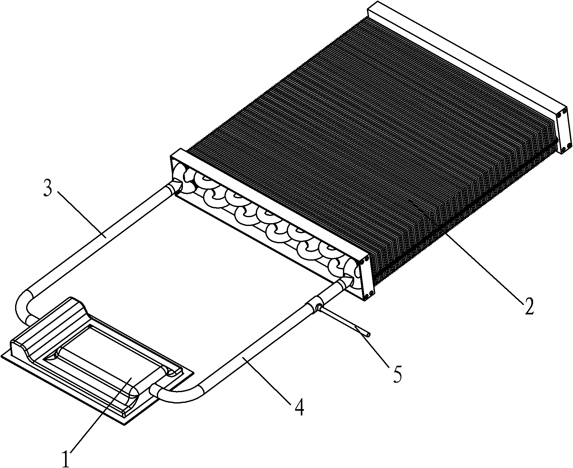
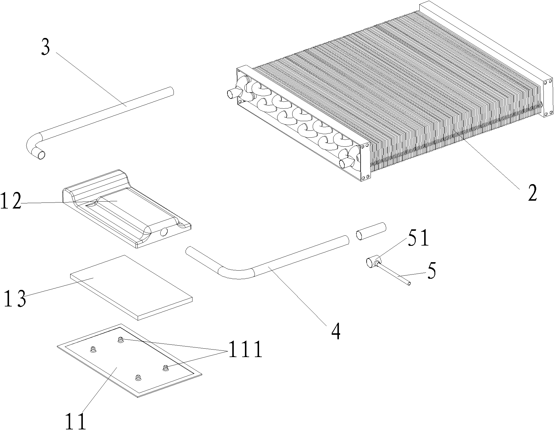
[0036] see figure 1 , figure 2 As shown, a high-power loop heat pipe radiator of the present invention mainly includes an evaporator 1, a condenser 2, and more than one steam pipeline 3 and a liquid pipeline 4 connecting the evaporator 1 and the condenser 2, and the liquid pipeline 4 It is also communicated with vacuumizing and working medium filling pipeline 5.

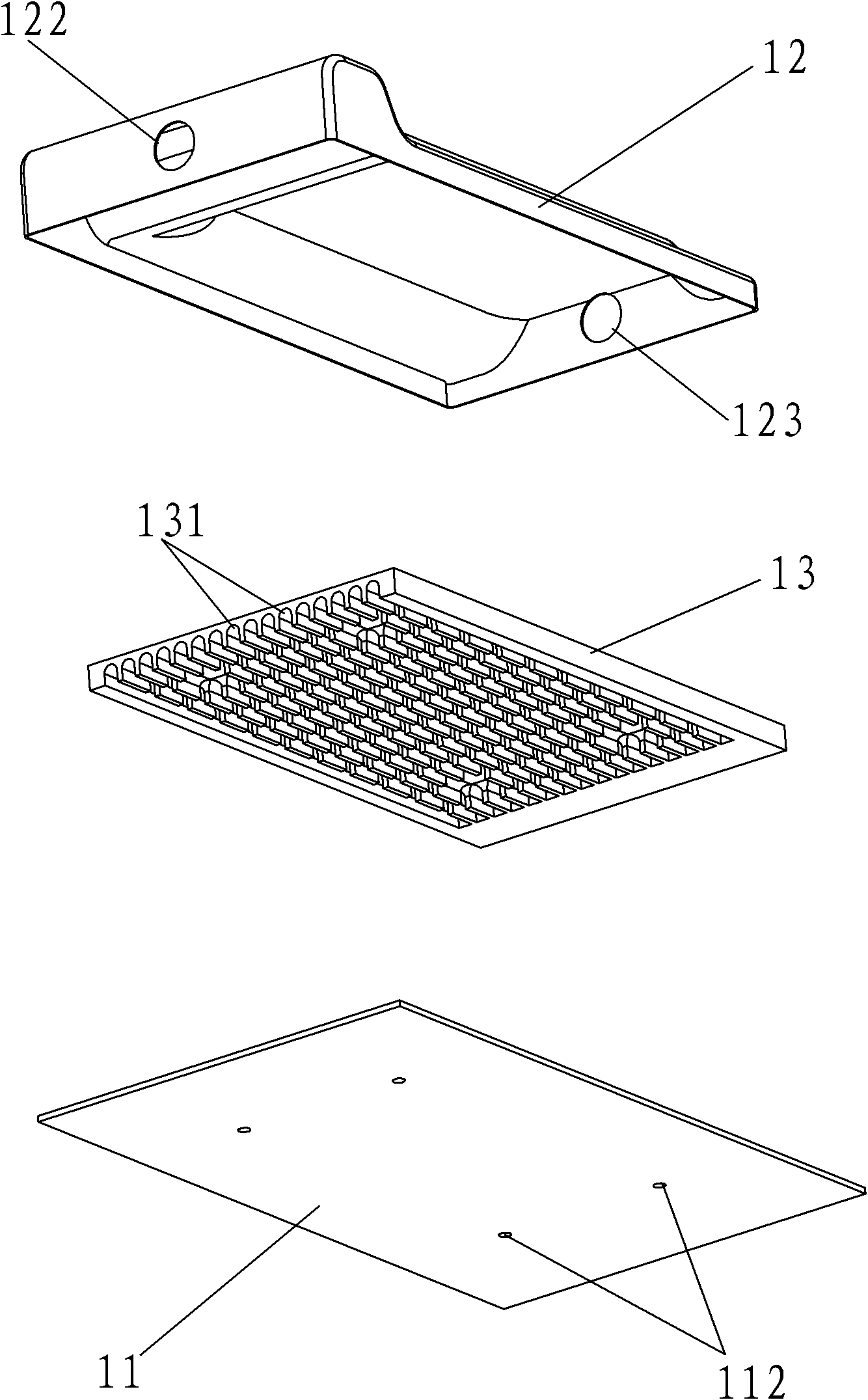
[0037] Among them, please refer to image 3 As shown, the evaporator 1 is a flat plate evaporator, which can be a nearly rectangular parallelepiped or a cube in shape, including a bottom plate 11 and an upper cover 12 fixedly connected, and a porous material 13 fixed between the bottom plate 11 and the upper cover 12 .

[0038] The bottom plate 11 is made of copper, aluminum or steel, with a boss 111 on the upper surface, and a blind screw hole 112 on the lower surface corresponding to the boss 111 . The function of the boss 111 is to meet the processing space of the blind-end screw hole 112 on the other side. Th...


PUM


Abstract

The invention relates to a high-power loop heat pipe radiator and a manufacturing method thereof. The radiator comprises a plate evaporator, a condenser, at least a steam line and at least a liquid line, wherein the steam line and the liquid line are used for connecting the plate evaporator with the condenser; the liquid line is also communicated with a vacuumizing and working medium filling line; a porous material is fixed inside the plate evaporator; and a plurality of communicated steam discharge channels are formed in the porous material. The manufacturing method comprises the following steps: preparing the porous material; stamping a top cover and a bottom plate of the plate evaporator; putting the porous material between the top cover and the bottom plate and fixedly connecting the top cover with the bottom plate; carrying out welding and communicating; and carrying out cleaning, vacuumizing, working medium filling and sealing. The radiator and the manufacturing method have the following advantages that: the radiation and installation use requirements of the high-power power electronic devices can be well met, the aim of full and effective contact with the power electronic devices can be achieved and the special evaporator structure further saves the space and is further beneficial to reinforcement of heat exchange, thus farthest reducing the radiating heat resistance.

Description

technical field [0001] The invention relates to a heat dissipation device in the field of power electronic products, in particular to a high-power loop heat pipe radiator and a manufacturing method thereof. Background technique [0002] Power electronics plays an important role in AC and DC motors, transportation, power systems, and power systems. At present, power electronic control technology has developed to the stage where IGBT and power integrated devices are the main technical means. IGBT (Insulated Gate Bipolar Transistor), that is, insulated gate bipolar transistor, is a composite fully-controlled voltage-driven power semiconductor device composed of a bipolar transistor and an insulated gate field effect transistor, with high input impedance and low conductance. Advantages in terms of pressure drop. It is very suitable for the conversion system with a DC voltage of 600V and above, such as AC motors, frequency converters, switching power supplies, lighting circuits...

Claims


Application Information

Patent Timeline
IPC IPC(8): H01L23/427H01L23/367H01L21/48F28D15/04F28D15/02
CPCH01L2924/0002F28D15/0266H01L2924/00
Inventor 李骥
Owner 北京芯铠电子散热技术有限责任公司
Why Eureka
Try Eureka