Permanent magnet synchronous motor drive control system

A permanent magnet synchronous motor, drive control technology, applied in the control system, vector control system, motor generator control, etc., can solve the problem that the motor parameters are easily affected by the outside world, cannot meet the high real-time requirements of the servo system, high real-time The current loop control is difficult to meet and other problems

Active Publication Date: 2011-08-17
BEIJING INSTITUTE OF TECHNOLOGYGY
View PDF5 Cites 32 Cited by
  • Summary
  • Abstract
  • Description
  • Claims
  • Application Information

AI Technical Summary

Problems solved by technology

In the early servo system, due to the poor performance of the microcontroller, it could not meet the high real-time requirements of the servo system, so the adjustment of the current loop was mostly realized by analog circuits, which caused the system performance to be affected by temperature drift, The influence of component aging factors is greater, and the reliability is lower
At the end of the 20th century, the performance of 8-bit and 16-bit single-chip microcomputers represented by MC51 and MC196 has been greatly improved compared with the early Z80 single-board microcomputer. However, it is still difficult to meet the high real-time current loop control.
The disadvantage of this method is that the use of PWM method will generate greater electromagnetic interference, which will bring greater noise impact to the upper control board and electrical system
[0005] In terms of controller algorithm, the PID controller is the most widely used controller in the closed-loop control system of the speed and position of the permanent magnet synchronous motor, but the permanent magnet synchronous motor is a nonlinear motor with the characteristics of multivariable and strong coupling. The parameters are easily perturbed by external influences, so the system is required to have a certain robustness, and the traditional PID controller cannot meet this requirement

Method used


Image

  • Permanent magnet synchronous motor drive control system
  • Permanent magnet synchronous motor drive control system
  • Permanent magnet synchronous motor drive control system

Examples


Embodiment

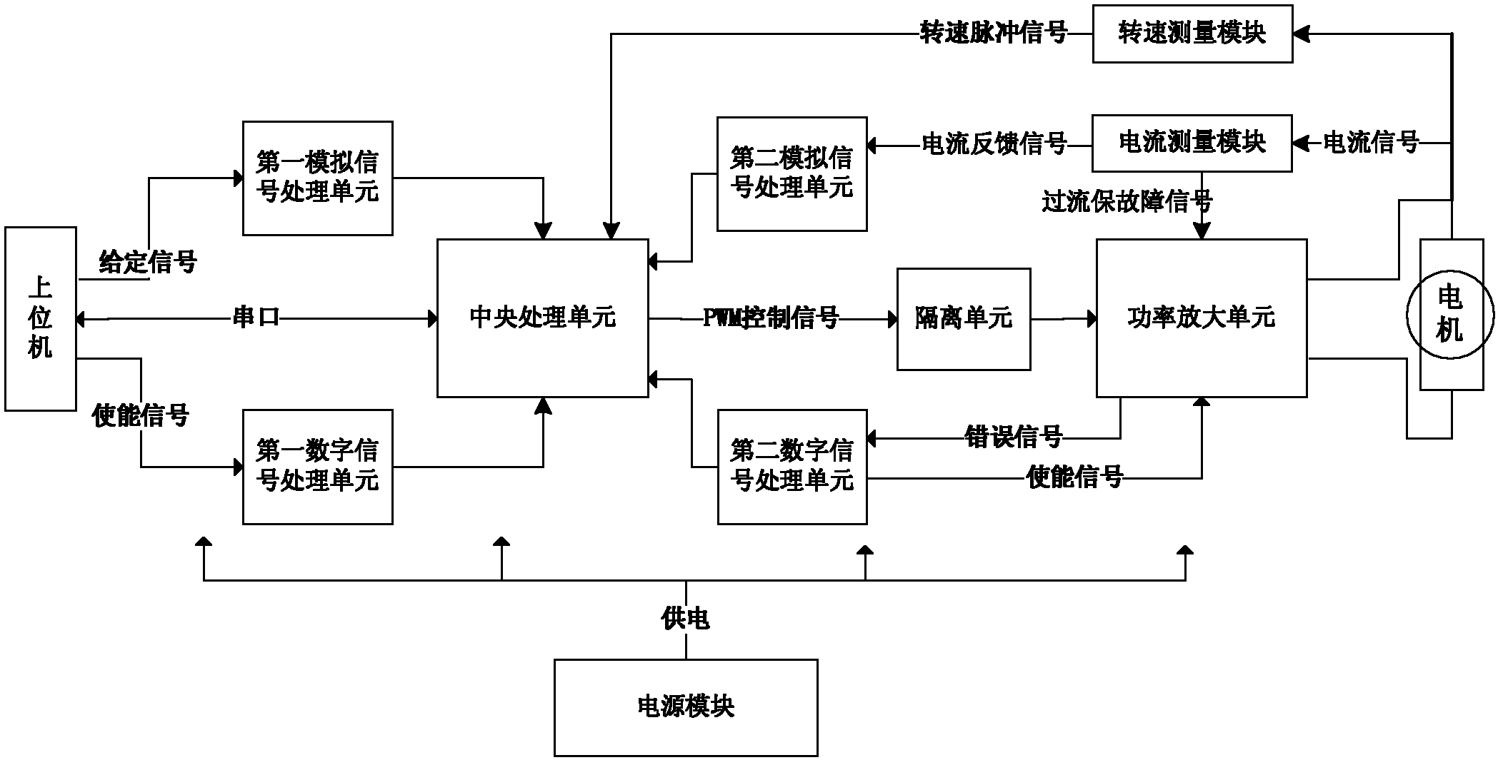
[0065] A permanent magnet synchronous motor drive control system, the peripheral equipment of which is a controlled motor and a host computer, consisting of a power supply module, a central control unit, 2 analog signal processing units, 2 digital signal processing units, a current measurement module, and a rotational speed measurement module , an isolation unit and a power amplifier unit;

[0066] The above power module adopts isolated power supply and is responsible for providing power to other departments;

[0067] The main control chip of the above-mentioned central control unit adopts the DSP chip of TI Company, the model is TMS320F2812;

[0068] The above isolation unit uses a high-speed optocoupler to achieve isolation, and the model of the high-speed optocoupler is 6N137;

[0069] The driving chip of the inverter bridge switching tube driving circuit in the above power amplification unit is IR2136;

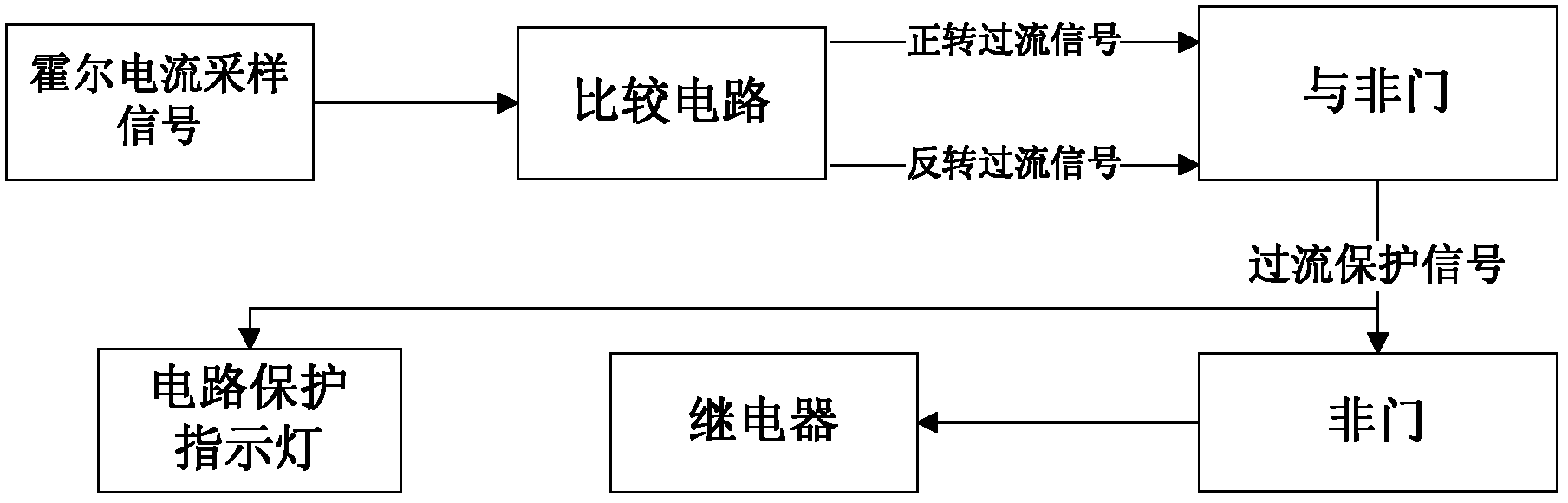
[0070] The functional block diagram of the above-mentioned overcurr...


PUM


Abstract

The invention relates to a permanent magnet synchronous motor drive control system, in particular to the permanent synchronous motor drive control system used for a servo system. The permanent synchronous motor drive control system belongs to the technical field of motor control. The permanent synchronous motor drive control system consists of a power module, a central control unit, two analogue signal processing units, two digital signal processing units, a current measurement module, a rotating speed measurement module, an overcurrent protection processing unit, an isolation unit and a power amplification unit. A drive strategy of the central control unit adopts a space vector pulse width modulation technology, and a speed loop controller with an integral time-varying sliding mode variable structure is designed in a digital signal processor (DSP) controller of the central control unit. Compared with the conventional control system, the permanent magnet synchronous motor drive control system has higher speed, enhanced anti-jamming capability and enhanced system parameter perturbation robustness; and the sliding mode of sliding mode variable structure control can be designed, and is insensitive to disturbance to the system and parameter variations, so the sliding mode variable structure control has the characteristics of high robustness, quick response, easily implemented comprehensive method and the like.

Description

technical field [0001] The invention relates to a drive control system of a permanent magnet synchronous motor, in particular to a drive control system of a permanent magnet synchronous motor used in a servo servo system, and belongs to the technical field of motor control. Background technique [0002] Permanent magnet synchronous motors have been widely used in various speed-adjusting driving occasions, especially in aerospace inertia due to their wide speed range, small torque fluctuation, fast response speed, high peak The occasions and fields that require high motor performance and control precision, such as actuator attitude control, robot, and turntable control, are generally valued. [0003] A typical follow-up servo system structure generally consists of a current loop, a speed loop and a position loop. The current loop control with the highest response speed is the inner loop, followed by the speed loop and position loop. If the servo system can realize the digit...

Claims


Application Information

Patent Timeline
Patent Type & Authority Applications(China)
IPC IPC(8): H02P21/14H02P21/00
Inventor 刘向东于玮陈振黄毅
Owner BEIJING INSTITUTE OF TECHNOLOGYGY
Why Eureka
Try Eureka