Transparent electrode

A transparent electrode and electrode layer technology, applied in the direction of gas discharge electrodes, circuits, electric light sources, etc., can solve the problems of high processing cost, easy to break, and unsuitable materials for transparent electrodes, etc., and achieve high conductivity and excellent heat resistance Effect

Active Publication Date: 2011-08-17
KOLON IND INC
View PDF0 Cites 3 Cited by
  • Summary
  • Abstract
  • Description
  • Claims
  • Application Information

AI Technical Summary

Problems solved by technology

However, there are problems with indium tin oxide (ITO) because the required processing costs are high because a vacuum process is required to form the ITO film, and because the ITO film is easily broken when the flexible display is bent or folded, the flexible display lifespan becomes short
However, since most organic conductive polymers so far absorb light in the visible range, they are not suitable as materials for transparent electrodes.

Method used


Image

  • Transparent electrode
  • Transparent electrode
  • Transparent electrode

Examples


Embodiment approach

[0048] Hereinafter, the present invention will be described in more detail with reference to the following examples. However, the scope of the present invention is not limited thereto.

[0049]

preparation example 1

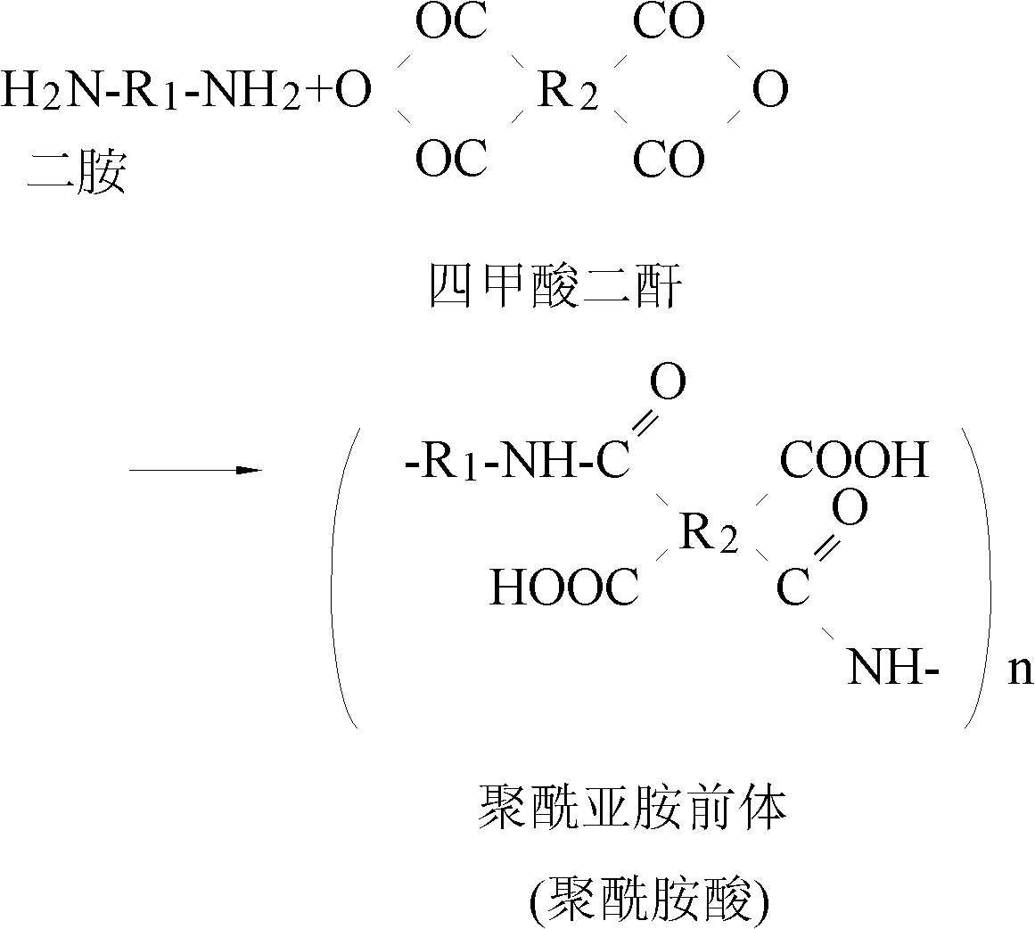
[0051] The polyimide precursor solution (solid content: 20%) was obtained by dissolving 2,2′-bis(trifluoromethyl)-4,4′-diaminobiphenyl ( 2,2'-TFDB), biphenyltetracarboxylic dianhydride (BPDA) and 2,2-bis(3,4-dicarboxyphenyl)hexafluoropropane dianhydride (6-FDA) by polycondensation. This reaction process is represented by Reaction Formula 1 below.

[0052] Reaction 1

[0053]

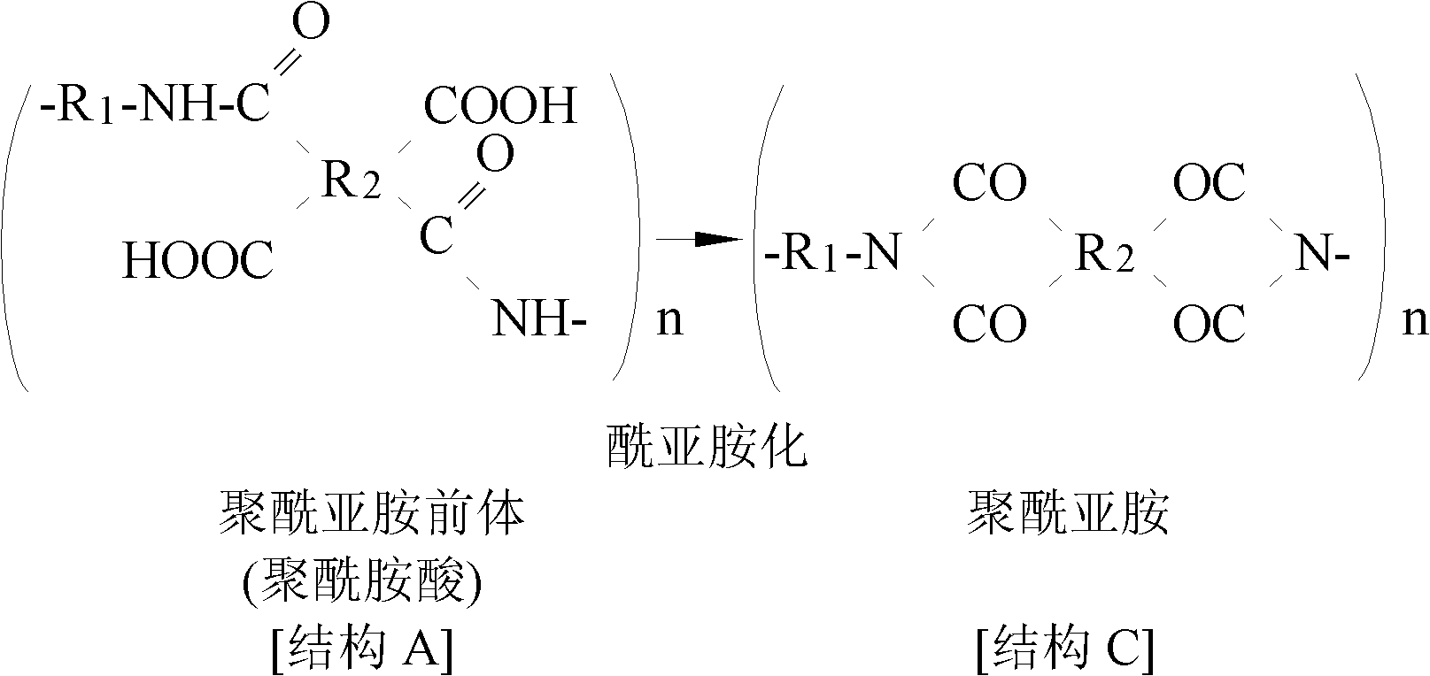
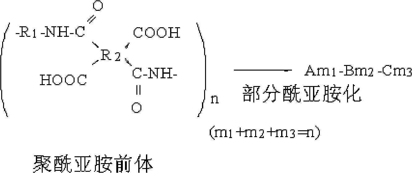
[0054] Subsequently, 2 to 4 equivalents of acetic anhydride (Samjeon Chemical Co., Ltd.) and pyridine (Samjeon Chemical Co., Ltd.) as a curing agent were respectively added to 300 g of the polyimide precursor solution to form a polyamic acid solution. Then, the polyamic acid solution is heated at a heating rate of 1-10°C / min for 2-10 hours to a temperature of 20-180°C to partially imidize (partially solidify) the polyamic acid solution, thereby preparing the polyamic acid solution containing part of imide A solution of an aminated (partially cured) intermediate.

[0055] Reaction Formula 2 below re...

preparation example 2

[0073] 34.1904 grams of N,N-dimethylacetamide (DMAc) was filled into a 100 mL three-necked round bottom flask as a reactor equipped with a stirrer, nitrogen sparger, dropping funnel, temperature controller and cooling reactor while passing nitrogen through the flask, then the reactor was cooled to 0°C, then 4.1051 g (0.01 mol) of 6-HMDA was dissolved in N,N-dimethylacetamide (DMAc) to form a first solution, and then the second A solution was maintained at 0°C. Subsequently, 4.4425 g (0.01 mol) of 6-FDA was added to the first solution to form a second solution, and then the second solution was stirred for 1 hour to completely dissolve 6-FDA in the second solution. In this case, the concentration of solid matter in the second solution was 20% by weight. Thereafter, the second solution was stirred at room temperature for 8 hours to obtain a polyamic acid solution having a viscosity of 2400 cps at 23°C.

[0074] After the reaction was completed, the obtained polyamic acid soluti...


PUM

PropertyMeasurementUnit
yellowness indexaaaaaaaaaa
thicknessaaaaaaaaaa
thicknessaaaaaaaaaa

Abstract

Disclosed herein is a transparent electrode, including: a polyimide film having an average linear thermal expansion coefficient of 50.0 ppm / DEG C or less, which is measured by thermo-mechanical analysis based on a film thickness of 50 to 100 [mu]m at a temperature of 50 to 250 DEG C, and a yellowness of 15 or less; and an electrode layer including a conductive material and a polyimide resin having an average linear thermal expansion coefficient of 50.0 ppm / DEG C or less, which is measured by thermo-mechanical analysis based on a film thickness of 50 to 100 [mu]m at a temperature of 50 to 250 DEG C, and a yellowness of 15 or less. The transparent electrode is advantageous in that a problem of a short circuit does not occur even when apparatuses including this transparent electrode are over-heated because it has excellent heat resistance, and in that it is transparent and has high electroconductivity.

Description

technical field [0001] The invention relates to a transparent electrode, in particular to a transparent electrode in which an organic electrode layer is formed on a plastic film. Background technique [0002] When computers, home appliances, and communication appliances are digitized and their performance is rapidly improved, there is a great need to realize large-sized portable displays. To realize portable large-area flexible displays, display materials need to be foldable and rollable like newspapers. [0003] Therefore, electrode materials in displays must not only be transparent and exhibit low impedance, but also exhibit high strength so that the device is mechanically stable even when bent or folded. In addition, electrode materials used in displays must have a thermal expansion coefficient similar to that of plastic substrates so that they do not short-circuit or their surface resistance does not change greatly even when the appliance is overheated or at a high temp...

Claims


Application Information

Patent Timeline
Patent Type & Authority Applications(China)
IPC IPC(8): H01B1/16
CPCH05B33/28H01B1/20H01J2211/225H01B1/24H01L51/5206Y10T428/24975H10K50/81H10K2101/00H01B1/16H05B33/10G02F1/1335H01J11/22
Inventor 郑鹤基金贞翰朴晓准宋相旻
Owner KOLON IND INC
Why Eureka
Try Eureka