Rake type vacuum drying system

A vacuum drying and raking technology, which is applied in the direction of non-progressive dryers, drying solid materials, drying, etc., can solve the problem of poor fluidity of lithium iron phosphate suspension, unsuitable drying of lithium iron phosphate material, and uneven product fineness and other problems, to achieve the effect of improving drying efficiency, occupying a small area, and uniform fineness

Active Publication Date: 2011-09-14
JIANGSU XIANFENG DRYING ENG
View PDF9 Cites 7 Cited by
  • Summary
  • Abstract
  • Description
  • Claims
  • Application Information

AI Technical Summary

Problems solved by technology

The rake-type vacuum dryer mentioned above is not suitable for drying lithium iron phosphate materials. This is due to the poor fluidity of lithium iron phosphate suspended materials. When drying, the materials change from liquid to paste to powder, and the material changes greatly. It is sticky, and the working resistance of the rake teeth is very large. For example, the rake rod and the rake teeth are not strong enough, and they are easy to bend and break during the drying process.
Moreover, the current welding between the hollow rake rod and the hollow main shaft causes a large deformation of the main shaft and the rake rod. When the main shaft drives the rake teeth to rotate, the gap between the head of the rake teeth and the inner wall of the tank is uneven. Affect the crushing effect, resulting in uneven product fineness
In addition, the finished product unloaded from the rake vacuum dryer needs to be transferred to another special equipment for cooling. The lithium iron phosphate product has high requirements on moisture and purity, and it is easy to absorb moisture and be polluted during the handling process.

Method used


Image

  • Rake type vacuum drying system
  • Rake type vacuum drying system
  • Rake type vacuum drying system

Examples


Embodiment 1

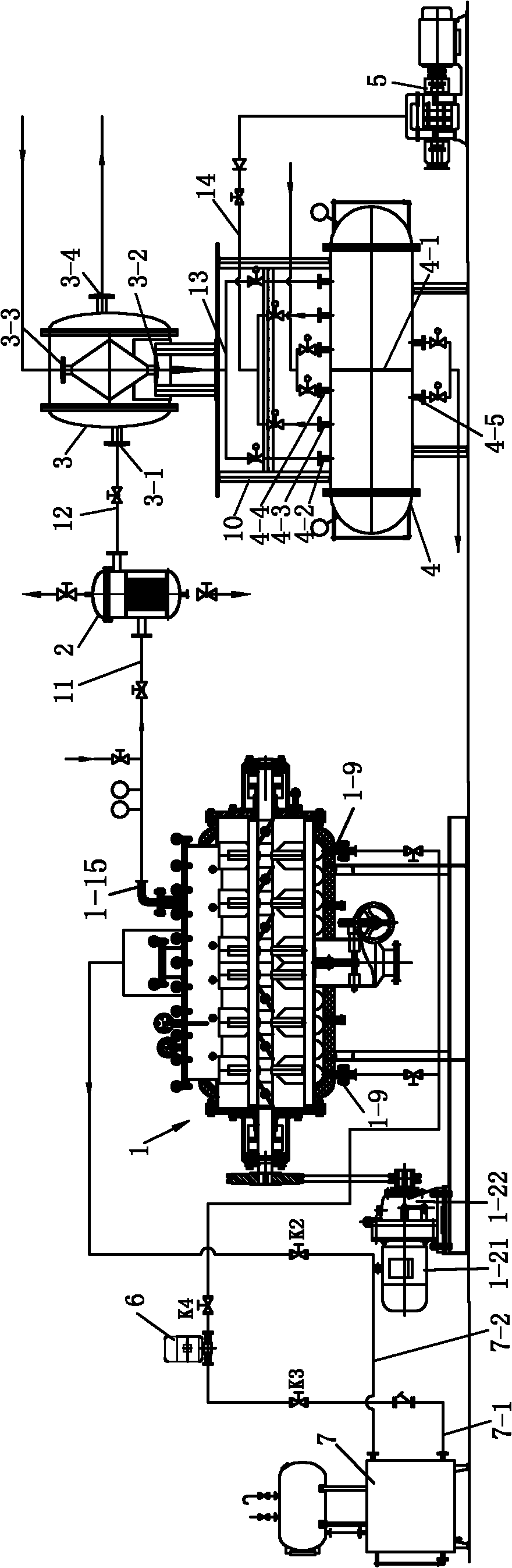
[0026] See Figure 1 to Figure 8 , a rake-type vacuum drying system, has a rake-type vacuum drying host 1, a bag filter 2, a condenser 3, a gas-liquid separator 4, a vacuum pump 5, an oil pump 6 and a thermal oil tank 7, and the thermal oil tank 7 is provided with Hot oil tank oil delivery pipe 7-1 and hot oil tank return oil pipe 7-2.

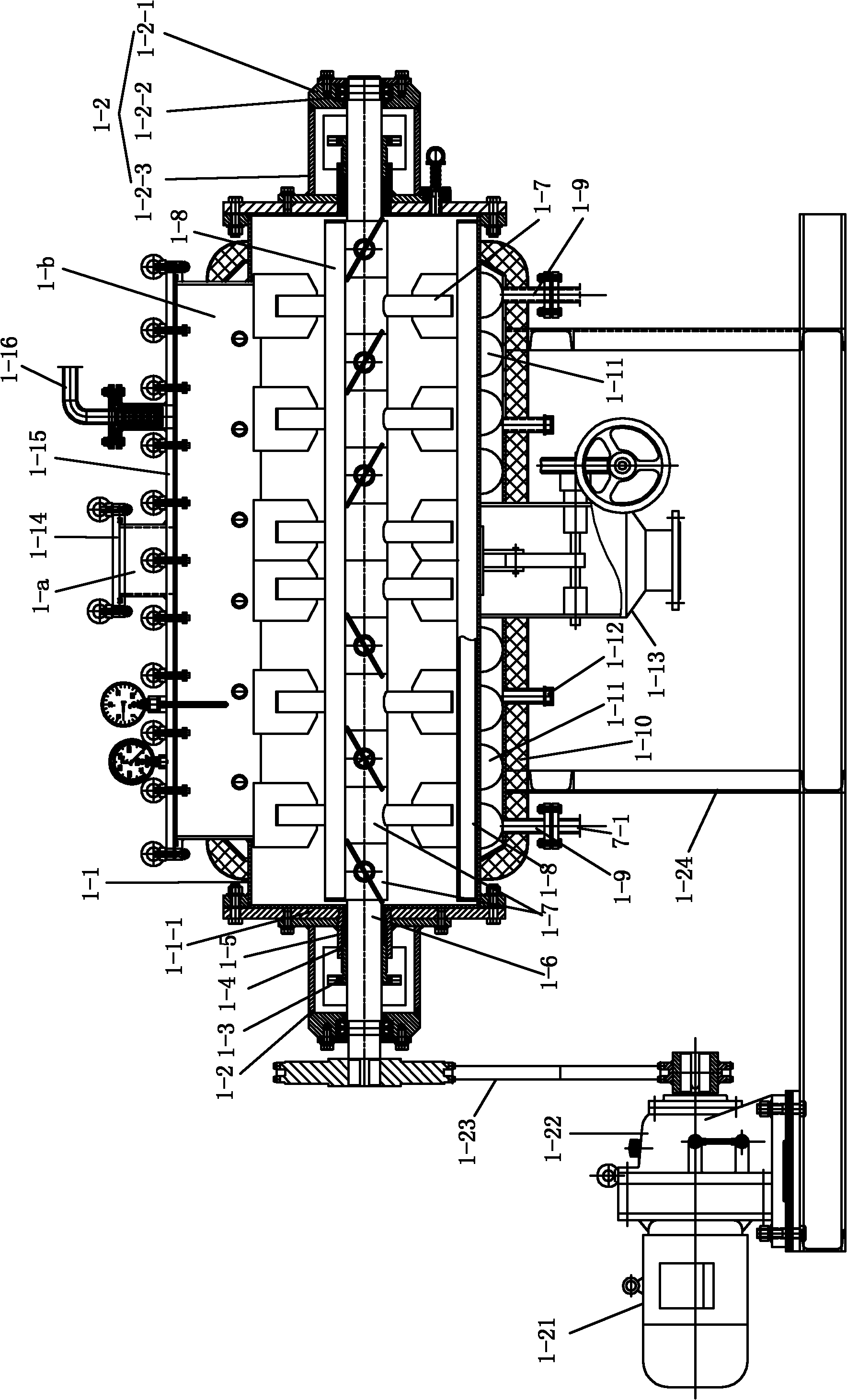
[0027] The rake type vacuum drying host 1 includes a motor 1-21, a reduction box 1-22, a saddle base 1-24, a jacketed tank 1-1 arranged on the saddle base 1-24 and a tank 1 Spindle 1-6 within -1. The output shaft of the reduction box 1-22 is connected with the above-mentioned main shaft 1-6 through a chain drive or a belt drive.

[0028] In order to facilitate maintenance and cleaning, the top of the tank body of the rake vacuum drying main machine 1 is provided with a manhole 1-b with a length greater than 1 / 2 of the tank body length, and a manhole 1-b that can be quickly opened and closed is provided on the manhole 1-b The cover plate 1-1...

Embodiment 2

[0037] On the basis of Embodiment 1, the present embodiment is also provided with a transfer oil tank 8 and a cold oil tank 9. The transfer oil tank 8 is an insulated oil tank. The transfer oil tank 8 is provided with a transfer oil tank oil delivery pipe 8-1 and a transfer oil tank return pipe 8-2. 9 is provided with a cold oil tank oil delivery pipe 9-1 and a cold oil tank return pipe 9-2, the transfer oil tank oil delivery pipe 8-1 is connected with the hot oil tank 7, the cold oil tank oil delivery pipe 9-1 is connected with the hot oil tank oil delivery pipe 7-1, and the transfer oil tank return oil pipe 8-2 and the oil return pipe 9-2 of the cold oil tank are connected with the oil return pipe 12. Each has a corresponding valve.

[0038] When working, the oil pump 6 is turned on, the valve K1 on the oil delivery pipe 8-1 of the transfer oil tank is normally open, the valve K2 on the return oil pipe 7-2 of the hot oil tank, the valve K 3 on the oil delivery pipe 7-1 of th...


PUM


Abstract

The invention provides a rake type vacuum drying system, which comprises a rake type vacuum drying host machine, a bag type filter, a condenser, a gas-liquid separator, a vacuum pump, an oil pump and a hot oil tank, wherein a main shaft of the rake type vacuum drying host machine is a solid main shaft; a plurality of rake tooth components are arranged on the main shaft; each rake tooth component comprises a sleeve shaft and four solid rake teeth uniformly distributed on the sleeve shaft in a fixed manner, and is connected on the main shaft through a sleeve shaft key; the rake teeth of the respective rake tooth components face towards the same direction, so that four passageways are formed in a tank body; and striking rods are respectively arranged in respective passageways or in spaced passageways. In the invention, materials inside the tank body of the drying host machine are struck continuously by using the striking rods, so that the crushing of the materials is accelerated, the materials can obtain larger specific surface areas, the drying process is accelerated, and finished products have uniform fineness and low water content; thus, the rake type vacuum drying system is suitable for drying lithium iron phosphate materials, and the product quality and drying efficiency are improved; moreover, the system is used for recovering solvents through the condenser and the gas-liquid separator, and is beneficial to reduction of the cost.

Description

technical field [0001] The present invention relates to a rake type vacuum drying system. Background technique [0002] The rake vacuum dryer is a general-purpose drying equipment. The rake vacuum dryer is a device that uses the characteristic that the boiling point of the water in the material decreases under vacuum to dry. The equipment is indirectly heated with a steam jacket, and the water is evaporated by heating and extracted in time. Inside the dryer shell, the rake teeth are driven by the transmission shaft. The end of the rake teeth and the axis are designed to have a certain angle. The transmission shaft rotates in the forward and reverse directions to move the material along the axial direction to facilitate drying and discharging. The Chinese Invention Patent Publication No. 101050916A discloses a rake dryer, which mainly adopts a hollow main shaft to be installed in the inner cylinder of the tank. The two ends of the hollow main shaft are respectively equippe...

Claims


Application Information

Patent Timeline
Patent Type & Authority Applications(China)
IPC IPC(8): F26B11/14F26B23/10F26B25/00F26B25/04
Inventor 谢洪清查协芳
Owner JIANGSU XIANFENG DRYING ENG
Why Eureka
Try Eureka