Systems and methods for gas supply and usage

A technology for supplying system and gas, applied in the field of gas (for example, it can solve the problems of difficult to automatically start and rise, difficult to adjust and maintain the minimum heating power and temperature, etc., to achieve long heater life, sensitive response, and fast system response. Effect

Inactive Publication Date: 2011-09-28
PRAXAIR TECH INC
View PDF12 Cites 6 Cited by
  • Summary
  • Abstract
  • Description
  • Claims
  • Application Information

AI Technical Summary

Problems solved by technology

[0007] Using only temperature and / or pressure as feedback parameters, the above systems are difficult to regulate and maintain the minimum heating power and temperature required to accommodate the user's product extraction rate
It is also difficult to automatically start and ramp up the system by using only temperature and / or pressure as feedback parameters

Method used


Image

  • Systems and methods for gas supply and usage
  • Systems and methods for gas supply and usage
  • Systems and methods for gas supply and usage

Examples


example 1

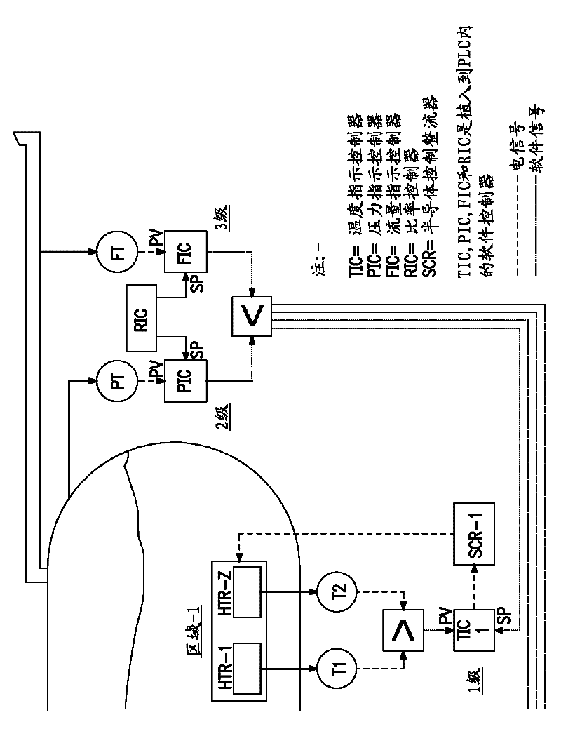
[0108] refer to figure 1 , this example describes a two-stage cascade control system that dynamically adjusts heating power in response to changes in user flow rate. In this two-stage cascade control system, only the pressure indicating controller (PIC) and the temperature indicating controller (TIC) are coupled. At a given time = 0 seconds, the vessel is warmed and the vessel pressure is stabilized at the PIC set point, eg, 120 psig. Steam flow to user site is zero (ie, BSGS is not working). As soon as the user starts drawing steam flow (eg, time = 0 seconds), the vessel pressure is immediately reduced to, eg, 119 psig. The PIC calculates an output signal based on the -1 psig difference between the vessel pressure and the PIC set point at this time. The output signal from the PIC corresponds to a change in the temperature set point of the TIC, in this case eg +10°F (ie, a 10°F increase in the TIC set point). The TIC then increases heating power to meet the new temperature...

example 2

[0110] refer to figure 1 , this example exemplifies a three-stage cascade control system that dynamically adjusts the heating power to the vessel in response to user flow rate changes. In this three-stage cascade control system, a pressure indicating controller (PIC), a temperature indicating controller (TIC) and a flow indicating controller (FIC) are all coupled. At a given time = 0 seconds, the vessel is warmed and the vessel pressure stabilizes at the PIC set point, eg, 120 psig. The steam flow rate stabilized at the FIC set point to the user site, eg 100 standard liters per minute (slpm). As soon as the user starts drawing steam flow (eg, 110 slpm, eg time = 0 seconds), the vessel pressure immediately decreases to eg 119 psig. The PIC calculates an output signal based on the -1 psig difference between the vessel pressure and the PIC set point at this time. The FIC also calculates an output signal based on the difference between the user steam flow rate and the FIC set p...


PUM


Abstract

The invention discloses systems and methods for gas supply and usage. This invention relates to gas vaporization and supply system that includes (a) a vessel suitable for holding a bulk quantity of a liquefied gas; (b) at least one heating source positioned on or near the vessel to supply energy to, or remove energy from, the liquefied gas; and (c) a heating source controller adapted to use process variables feedback for dynamically regulating the heating source and maintaining and regulating gas output. The process variables feedback results from cascading sequence control of at least two process variables. The process variables include pressure, temperature, and / or gas output flow rate. This invention also relates to a method for delivery of a gas, e.g., ultra high purity gases, from a liquefied state in a controlled manner to a usage site, e.g., a semiconductor manufacturing facility. This invention provides faster heating system response to fluctuations in customer demand, a longer heater life, and improved reliability.

Description

technical field [0001] The present invention relates to gas (eg, ultra-high purity gas) evaporation and supply systems and methods of delivering the gas in a liquefied state to the site of use (eg, semiconductor manufacturing equipment) in a controlled manner. The systems and methods use process variable feedback (ie, temperature, pressure, and / or gas output flow rate) for dynamically adjusting the heat source and maintaining and adjusting the gas output to the field of use. Background technique [0002] The growth of the electronics industry has created a demand for a large supply of ultra-high purity (UHP) gases. Molecules such as ammonia and silanes are used in the electronics industry for different applications. For example, ammonia is one of the main gases used in metal-organic chemical vapor deposition (MOCVD) for gallium nitride film growth. For certain gases (eg, NH 3 ) flow rate requirements have increased due to developments in LCD and LED manufacturing at 300 m...

Claims


Application Information

Patent Timeline
Patent Type & Authority Applications(China)
IPC IPC(8): F17C7/04
CPCY02E60/321F17C2250/0439F17C2223/035F17C2201/056F17C2227/0381F17C2227/0302F17C2250/0694F17C2250/0443F17C2201/054F17C9/02F17C2250/0626F17C2223/0153F17C2260/023F17C2203/0643F17C2250/0636F17C2250/0631F17C2223/033F17C2270/0518F17C2250/043F17C2221/05F17C2203/0648F17C2227/0386F17C2265/012F17C2221/012F17C2223/0115F17C2223/038F17C2250/032Y02E60/32F17C7/04F17C9/04F17C13/04
Inventor J.C.格蒙K.L.伯格斯C.萨里伊安尼季斯M.D.麦凯恩K.R.佩斯H.朱H.E.法拉
Owner PRAXAIR TECH INC
Why Eureka
Try Eureka