A kind of cleaning method and device of fouling membrane

A technology of forward osmosis membrane and drawing liquid, which is applied in the field of membrane separation to achieve the effect of reducing operating costs, high cleaning efficiency, and shortening cleaning time

Inactive Publication Date: 2011-12-21
TIANJIN POLYTECHNIC UNIV
View PDF5 Cites 10 Cited by
  • Summary
  • Abstract
  • Description
  • Claims
  • Application Information

AI Technical Summary

Problems solved by technology

[0005] Table 1 Working principle and disadvantages of existing membrane cleaning methods

Method used


Image

  • A kind of cleaning method and device of fouling membrane
  • A kind of cleaning method and device of fouling membrane
  • A kind of cleaning method and device of fouling membrane

Examples


Embodiment 1

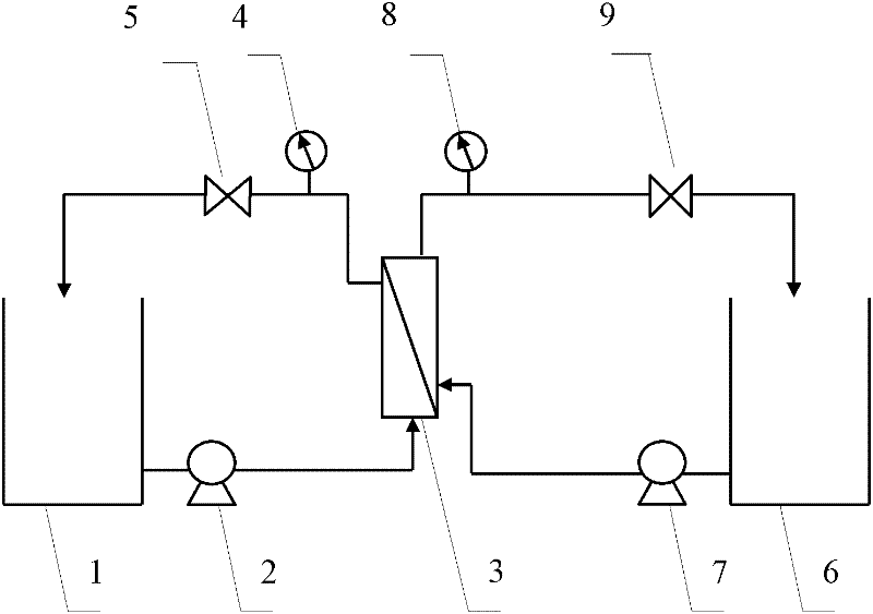
[0034] A 1M ammonium bicarbonate solution and a 3M ammonium hydroxide solution were mixed at a ratio of 1.2:1 to prepare a drawing solution, and distilled water was used as a raw material solution. The raw material liquid is on the cortex side of the polluted hollow fiber membrane (referred to as polluted membrane), and the draw solution is on the support layer side of the polluted membrane. The cross-flow rate of the feed solution and the draw solution was maintained at 2.0 L / min, and both were operated at room temperature. Put the polluted membrane to be cleaned into the forward osmosis membrane module 3, turn on the power, open the raw material liquid valve 5 and the draw liquid valve 9 respectively, and start the diaphragm pump 2 and the peristaltic pump 7 respectively, and adjust the pressure gauge so that the raw material liquid pressure The indications of Table 4 and the drawing hydraulic pressure gauge 8 are kept at 0.2MPa. The diaphragm pump 2 presses the distilled w...

Embodiment 2

[0036] The 5M fructose solution was used as the drawing solution, and distilled water was used as the raw material solution. The raw material solution was on the cortex side of the polluted membrane, and the drawing solution was on the support layer side of the polluted membrane. The cross flow rate of the two was 2.0L / min. The raw material solution and the drawing solution The temperature was heated to 50°C, and the rest was the same as that described in Example 1, and the power was turned off after 0.5h of operation. A completely cleaned membrane can be obtained.

Embodiment 3

[0038] Mix 5M sucrose solution and 1M sodium chloride solution at a ratio of 2:1 to prepare a drawing solution, use distilled water as the raw material solution, control the cross-flow rate of the raw material solution and the drawing solution at 100ml / min, and keep the experimental temperature at 25 ± At 2°C, the feed solution is on the skin side of the fouled membrane, and the draw solution is on the support layer side of the fouled membrane. The rest are the same as the method described in Example 1, run for 0.5h, and then turn off the power supply to obtain a completely cleaned membrane.


PUM


Abstract

The invention discloses a method and a device for cleaning a polluted membrane. The cleaning method adopts two circulation systems of raw material liquid and drawing liquid. The raw material liquid with low osmotic pressure is "absorbed" by the high osmotic drawing liquid, and the membrane cavity will be polluted when the raw material liquid enters the drawing liquid. The impurities on the surface of the cortex and the impurities adsorbed in the porous support layer are taken away to realize the thorough cleaning of the polluted membrane; the raw material liquid circulation system and the draw liquid circulation system are prepared in cross-flow at the forward osmosis membrane module, and the cleaning cycle rate is 2.0-3.0L/ min, the cleaning pressure is 0.2MPa, the cleaning temperature is room temperature, and the cleaning time is 20-30min; the raw material liquid is distilled water; the drawing liquid includes inorganic salt solution, sugar solution or a mixture of inorganic salt and sugar solution. The cleaning device is suitable for the cleaning method of the present invention, and includes two circulation systems of raw material liquid and drawing liquid, and the two circulation systems are prepared in cross-flow at the forward osmosis membrane module.

Description

technical field [0001] The invention relates to membrane separation technology, in particular to a cleaning method and device for polluted membranes. Background technique [0002] Membrane fouling refers to the physical and chemical interaction between certain components of the separated substance and the membrane, or the concentration of the solute on the membrane surface exceeds its solubility due to concentration polarization, and the contamination on the membrane surface or in the membrane pores caused by mechanical action. The adsorption and deposition of the membrane will cause the membrane pore size to become smaller or clogged, which will cause the phenomenon of irreversible changes in the permeation flow rate and separation characteristics of the membrane. Although membrane separation wastewater treatment technology has been more and more widely used, membrane fouling has become a bottleneck restricting the further development and application of membrane separation ...

Claims


Application Information

Patent Timeline
Patent Type & Authority Applications(China)
IPC IPC(8): B01D65/02
Inventor 王薇田恩玲孙静于湉
Owner TIANJIN POLYTECHNIC UNIV
Why Eureka
Try Eureka