Closed-loop controlled-pressure well drilling system

A managed pressure drilling and control system technology, applied in earthwork drilling, wellbore flushing, wellbore/well components, etc., can solve the problems of unfavorable popularization and application, waste of manual throttling manifold, high selectivity and dependence, etc. Achieve the effects of avoiding repeated installation of sensors, convenient on-site application, and strong system adaptability

Active Publication Date: 2012-02-22
BC P INC CHINA NAT PETROLEUM CORP +1
View PDF7 Cites 52 Cited by
  • Summary
  • Abstract
  • Description
  • Claims
  • Application Information

AI Technical Summary

Problems solved by technology

[0005] 1. There are two ways to obtain the engineering data (such as pumping flow rate, vertical pressure, well depth and other process parameters) required by the existing MPD system. One is from the reinstalled sensors on the well site equipment, which will lead to The well site sensors are installed repeatedly, and the well site has an integrated mud logging system, or the drilling rig itself has a data acquisition system, so there is no need for repeated wasteful installation; the second is to manually input the key engineering parameters required, such as well depth, etc., which cannot be achieved For the purpose of real-time, the wellhead control pressure calculated by hydraulics is inaccurate, and requires personnel to input data from time to time, which is labor-intensive, and may cause wrong instructions to control casing pressure due to human error, which may lead to drilling accidents. Even if the managed pressure drilling system of some companies is compatible with the integrated mud logging system, it can only be compatible with the integrated mud logging system of a specific data format. application
[0006] 2. At present, if there is a problem with the upper computer, transmission data line or communication of the managed pressure drilling system, the ground pressure execution equipment (back pressure compensation, automatic throttle manifold) will lose the automatic control signal and cannot be automatically controlled, which may cause control failure. Increased well control and equipment risk;
[0007] 3. The surface pressure automatic control system cannot be split into independent units for on-site application. The whole set of equipment must be put on the well site, including back pressure compensation, automatic choke manifold, numerical control room, etc., which is selective for the size of the well site and limits the Its application range; and the on-site debugging after the equipment is manufactured also needs to go to the site, which increases the cost and is inconvenient for equipment debugging; and the current high cost of the managed pressure drilling system limits its popularization and application
[0008] 4. At present, the control of the automatic choke manifold of the domestic and foreign MPD systems adopts the hydraulic control method. The main problems are: 1. The hydraulic choke control can realize automatic control, although the labor of personnel is reduced to a certain extent. strength, but the hydraulic control cannot be improved on the original choke manifold, and the choke manifold must be redesigned and manufactured, resulting in a lot of waste of the existing manual choke manifold; 2. If a foreign hydraulic control cho...

Method used


Image

  • Closed-loop controlled-pressure well drilling system
  • Closed-loop controlled-pressure well drilling system
  • Closed-loop controlled-pressure well drilling system

Examples


Embodiment 1

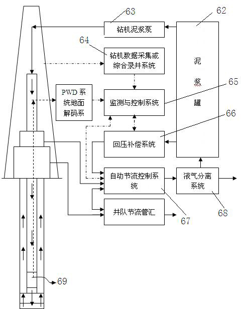
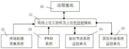
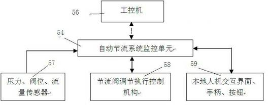
[0059] A closed-loop pressure-controlled drilling system, including an annular pressure monitoring system, a rotary control head, and a liquid-gas separation system, and also includes a monitoring and control system, an automatic throttling control system, and a back pressure compensation system. The flow control system is connected to the back pressure compensation system; the monitoring and control system includes an upper industrial control detection mechanism, an automatic throttling system monitoring unit and a back pressure compensation system monitoring unit, and the upper industrial control detection mechanism is connected with the automatic throttling system monitoring unit respectively Connect with the monitoring unit of the back pressure compensation system.

[0060] The monitoring and control system among the present invention is described below:

[0061] The upper industrial control monitoring mechanism includes an industrial computer, a network communication devi...

Embodiment 2

[0087] The present invention is described in detail below:

[0088] 1. The specific implementation steps of the closed-loop pressure control drilling system are as follows:

[0089] 1) The upper industrial control detection mechanism includes: industrial computer, network communication equipment and communication interface, industrial computer and well site data acquisition system local area network, PWD system ground decoding software. The industrial computer establishes an industrial local area network through network communication equipment. The interface is respectively connected with the monitoring unit of the automatic throttling system and the monitoring unit of the back pressure compensation system; the well site data acquisition system mainly includes the integrated mud logging system and the data acquisition and monitoring system of the drilling rig itself; through the network interface and the host computer software and interface, it can Real-time sharing of enginee...

Embodiment 3

[0118] The automatic throttling control system in the present invention can also be a hydraulically controlled automatic throttling control system, and the following describes the use of a hydraulically controlled automatic throttling control system:

[0119] The hydraulic control automatic throttling control system includes automatic throttling manifold, electric hydraulic throttling control actuator and monitoring control system:

[0120] The throttling manifold mainly includes: three automatic throttling control channels, consisting of three hydraulically controlled throttling devices and six plate valves, one emergency manual throttling control channel, consisting of one throttle valve and two plate valves The emergency pressure relief straight channel is composed of a flat valve, and there are two parallel channels in front of the outlet, which are composed of three flat valves and U-shaped outlet flowmeters. The four channels are connected in parallel to form a set of thr...


PUM


Abstract

The invention discloses a closed-loop controlled-pressure well drilling system, which comprises an annular pressure monitoring system, a rotary control head, a liquid-gas separation system, a monitoring and controlling system, an automatic throttle control system and a back pressure compensation system, wherein the monitoring and controlling system is respectively connected with the automatic throttle control system and the back pressure compensation system; the monitoring and controlling system comprises a superior industrial control detection mechanism, an automatic throttle system monitoring unit and a back pressure compensation system monitoring unit; and the superior industrial control detection mechanism is respectively connected with the automatic throttle system monitoring unit and the back pressure compensation system monitoring unit. Through precise pressure control, bottom-hole pressure is precisely controlled to reach a target pressure.

Description

technical field [0001] The invention relates to a closed-loop pressure-controlled drilling system, which is used for precise control of wellbore pressure to ensure that the annular pressure profile of the wellbore is at a set value, and belongs to the field of drilling pressure control in oil and gas fields. Background technique [0002] In recent years, with the intensification of oil and gas exploration and development, drilling in various complex areas is increasing, and the application of conventional overbalance pressure control technology can no longer meet the needs of complex areas in piedmont, safe drilling in narrow density windows, and H-containing areas. 2 Production requirements such as drilling in S gas layers, shrinkage sticking caused by high-density mud leakage, and well control risks, because the bottomhole pressure control mainly depends on the traditional method, that is, the adjustment of drilling parameters such as controlling the performance of drilling...

Claims


Application Information

Patent Timeline
IPC IPC(8): E21B21/12E21B21/08E21B47/00E21B47/12
Inventor 李枝林孙海芳韩烈祥肖润德董斌杨玻唐贵薛秋来魏强唐国军左星潘登
Owner BC P INC CHINA NAT PETROLEUM CORP
Why Eureka
Try Eureka