Microflow sensor
A flow sensor, miniature technology, applied in the field of MEMS devices, can solve the problems of high power consumption and long response time of flow sensors, and achieve the effect of light weight, high sensitivity and stable performance
- Summary
- Abstract
- Description
- Claims
- Application Information
AI Technical Summary
Problems solved by technology
Method used
Image

Examples
Embodiment 1
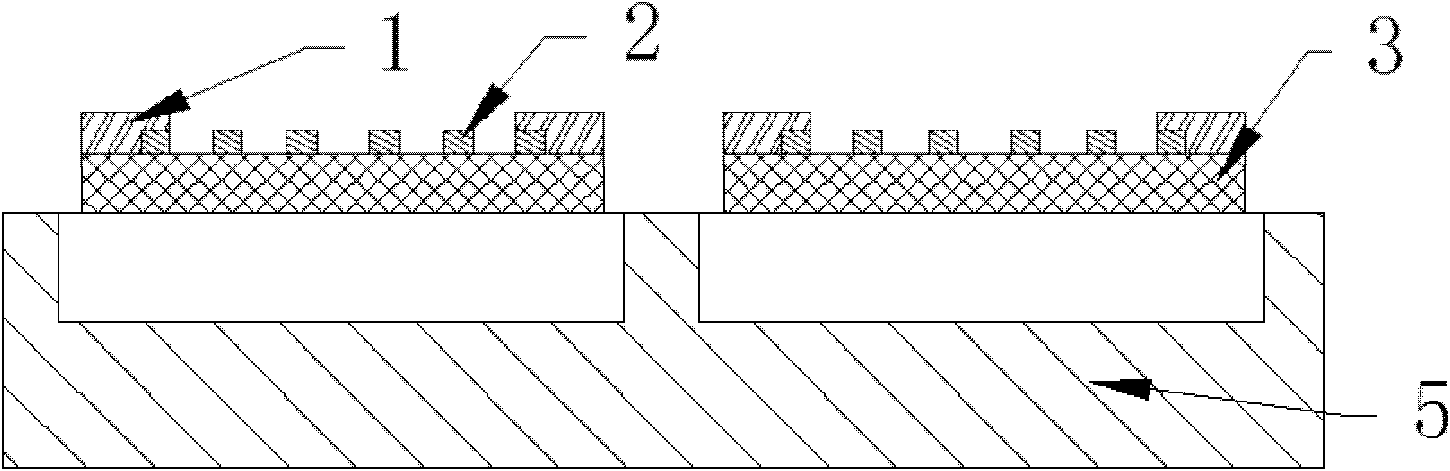
[0044] Example 1, such as figure 1 As shown, it includes a substrate 5, an insulation layer 4 and a heating body 2. The substrate 5 has a groove, and the surface of the groove is framed with two separate insulation layers 4, and the heating body 2 is sputtered on the insulation layer 4. , The two ends of the heating body 2 are sputtered with metal electrodes 1;
[0045] The material of the substrate 5 is polysilicon;
[0046] The material of the heat insulation layer 4 is silicon nitride, which is deposited on the substrate 5 by a chemical vapor deposition (LPCVD) process, with a thickness of 1 μm;
[0047] The heating body is nickel metal with a curved shape;
[0048] The metal electrode is formed by sputtering a Pt layer on the surface of the Ti adhesion layer and then sputtering an Au layer.
Embodiment 2
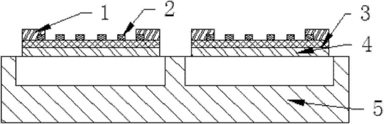
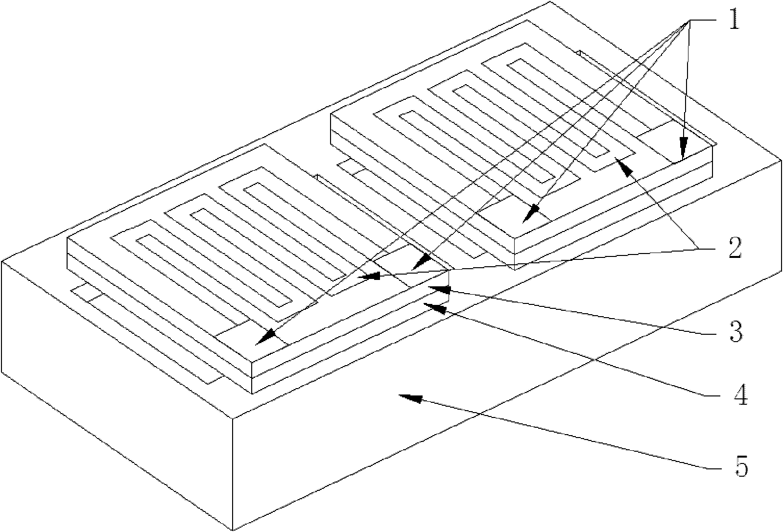
[0049] Example 2, such as figure 2 , image 3 As shown, it includes a substrate 5, an insulation layer 4, an insulation layer 3, and a heating body 2. The substrate 5 has a groove. The surface of the groove is framed with two separate insulation layers 4, and the surface of each insulation layer is covered with insulation. Layer 3, a heating body 2 is sputtered on the insulating layer 3, and metal electrodes 1 are sputtered on both ends of the heating body 2;
[0050] The material of the substrate 5 is monocrystalline silicon;
[0051] The material of the heat insulation layer 4 is silicon nitride with a thickness of 1 μm;
[0052] The material of the insulating layer 3 is silicon dioxide with a thickness of 250 nm;
[0053] The heating body is nickel metal with a curved shape;
[0054] The metal electrode is composed of Au layer sputtered on the surface of the Ti adhesion layer.
[0055] The preparation method of this embodiment includes the following steps in sequence:
[0056] (1) As...
Embodiment 3
[0060] Example 3, such as figure 2 , image 3 As shown, it includes a substrate 5, an insulation layer 4, an insulation layer 3, and a heating body 2. The substrate 5 has a groove. The surface of the groove is framed with two separate insulation layers 4, and the surface of each insulation layer is covered with insulation. Layer 3, a heating body 2 is sputtered on the insulating layer 3, and metal electrodes 1 are sputtered on both ends of the heating body 2;
[0061] The material of the substrate 5 is glass;
[0062] The material of the heat insulation layer 4 is silicon nitride with a thickness of 1 μm;
[0063] The material of the insulating layer 3 is silicon dioxide with a thickness of 250 nm;
[0064] The heating body 2 is Pt metal with a curved shape;
[0065] The metal electrode 1 is composed of an Al layer sputtered on the surface of the Ti adhesion layer;
[0066] The preparation method of this embodiment includes the following steps in sequence:
[0067] (1) As shown in Figur...
PUM
 Abstract
Description
Claims
Application Information
 - R&D
- Intellectual Property
- Life Sciences
- Materials
- Tech Scout
- Unparalleled Data Quality
- Higher Quality Content
- 60% Fewer Hallucinations
Browse by: Latest US Patents, China's latest patents, Technical Efficacy Thesaurus, Application Domain, Technology Topic, Popular Technical Reports.
© 2025 PatSnap. All rights reserved.Legal|Privacy policy|Modern Slavery Act Transparency Statement|Sitemap|About US| Contact US: help@patsnap.com