
Fuel injection control system of flexible fuel engine

A control system and flexible fuel technology, applied in the direction of fuel injection control, engine control, machine/engine, etc., can solve the problem of inability to take into account intake port injection and in-cylinder direct injection, complex control strategies, inability to flexibly select different fuels, etc. problem, achieve simple and effective lean burn and stratified burn, realize lean burn and stratified burn, and improve fuel economy

Inactive Publication Date: 2012-04-18
镇江恒驰科技有限公司
View PDF17 Cites 8 Cited by
  • Summary
  • Abstract
  • Description
  • Claims
  • Application Information

AI Technical Summary

Problems solved by technology

[0014] For the currently published flexible fuel engines, usually including two sets of electronic control units, the whole system structure is relatively complex, the manufacturing cost is high and the control is difficult; usually a single port injection or direct injection in the cylinder is used, Can not take into account the advantages of port injection and in-cylinder direct injection; the function of the whole system is relatively single, or simply improve the emission of the engine, or simply improve the cold start of the engine, or simply avoid the occurrence of engine knocking, etc.
For the current dual-system internal combustion engines, they usually share a low-pressure oil circuit or fuel rail, and cannot flexibly select different fuels for work, and the control strategy of the entire system is relatively complicated, and the functions realized are relatively single

Method used


Image

  • Fuel injection control system of flexible fuel engine
  • Fuel injection control system of flexible fuel engine

Examples


Embodiment Construction

[0037] In conjunction with the accompanying drawings, the present invention will be further described through the embodiments.

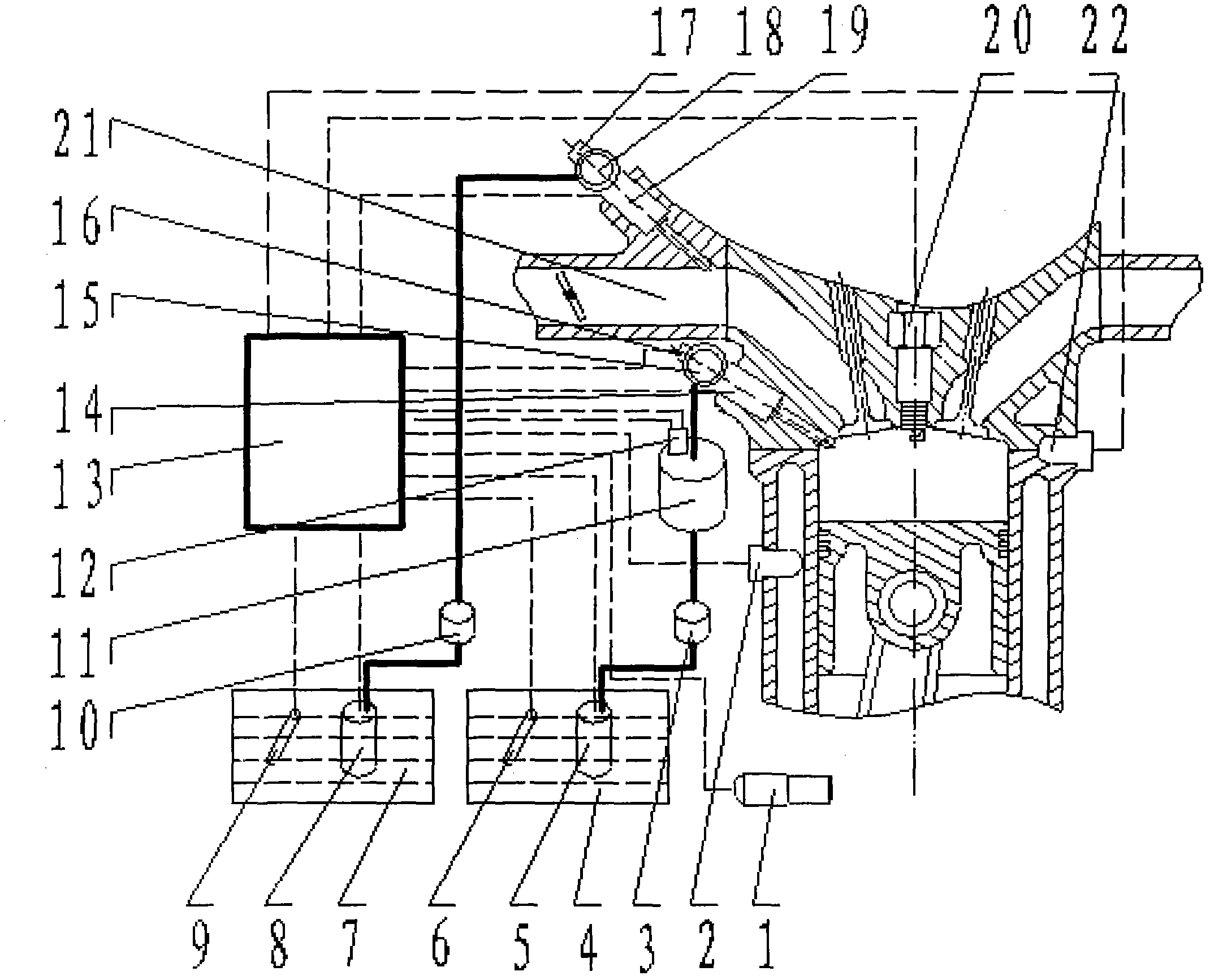
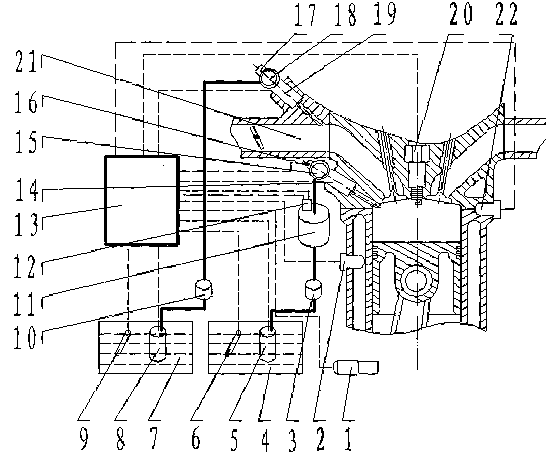
[0038] Accompanying drawing shows the schematic diagram of the fuel injection control system of the flexible fuel engine that the present invention announces, comprises intake duct (21), engine temperature sensor (2), crankshaft position sensor (1), electronic control unit (13), knocking Sensor (22), spark plug (20) and fuel tank I (7), low-pressure fuel pump I (8), liquid level sensor I (9), fuel filter I (10), low-pressure fuel pressure regulating valve I (17), The intake port injection (PI) system composed of PI rail I (18) and PI injector I (19) also includes oil tank II (4), low-pressure oil pump II (5), liquid level sensor II (6), Fuel filter II(3), in-cylinder direct injection high-pressure fuel pump II(11), high-pressure oil circuit electronically controlled pressure regulator II(12), DI fuel rail II(15), DI fuel rail pressure sensor II(16) ...


PUM


Abstract

The invention provides a fuel injection control system of a flexible fuel engine and belongs to the field of control of engines. The system is characterized in that the flexible fuel engine with an independent PI (port injection) system and an independent DI (direct injection) system is coordinatively controlled through an electronic control unit, so that the PI system and the DI system can operate simultaneously and also can operate independently; when the engine is started, the PI system operates independently; through detecting signals of a liquid level sensor I, an engine temperature sensor and a crank shaft position sensor, the electronic control unit judges whether the DI system operates or not, if conditions are met, the DI system can operate normally; the fuel injection amount and injection timing of the PI system and the DI system as well as the ignition timing and ignition energy storage period of a spark plug are regulated; through the principle of calibrating the fuel charge pulse spectrum of the PI system and the DI system based on equal heat energy of a gasoline engine with an equal output volume and by virtue of the accurate design and assembly of installation positions of a DI fuel injector and the spark plug as well as a corresponding control strategy, thin and layered combustion can be realized, detonation can be avoided, the fuel economy is improved and the emission is reduced.

Description

technical field [0001] The invention belongs to the field of engine control, in particular to a fuel injection control system of a flexible fuel engine. Background technique [0002] With the increasing scarcity of oil resources, the problem of automobile energy will affect all areas of the national economy. In order to solve the energy problem of automobiles, various new fuel engines have come out one after another, such as hydrogen fuel engines, ethanol gasoline E80 engines, CNG engines and LPG engines. The emergence of new fuel engines will ease the dependence on oil. However, due to the incomplete construction of new fuel infrastructure and inconvenient refueling, its application range is restricted. Therefore, countries all over the world are gradually increasing the research and development of flexible fuel engines. [0003] The Chinese invention of the patent (application number: 200710141489.4 announcement number: CN 10052203C) discloses a flexible fuel engine con...

Claims


Application Information

Patent Timeline
IPC IPC(8): F02D41/38
Inventor 张育华崔慧峰
Owner 镇江恒驰科技有限公司
Learn More