
Pattern transfer method and apparatus therefor

A pattern transfer and pattern technology, applied in transfer printing, printed circuit manufacturing, rotary printing machines, etc., can solve the problems of uneven pattern boundary, uniform pattern, difficult alignment of mask and target, etc.

Inactive Publication Date: 2012-05-16
KOREA ADVANCED INST OF SCI & TECH
View PDF6 Cites 27 Cited by
  • Summary
  • Abstract
  • Description
  • Claims
  • Application Information

AI Technical Summary

Problems solved by technology

That is, the manufacturing process is complicated, the shadow mask is difficult to manufacture, the manufacturing cost is high, and the accuracy is lowered due to the distortion of the mask.
In addition, it has the disadvantages that it is difficult to align the mask and the target, and it is difficult to change the process, that is, to change the size and shape of the pattern.
[0005] Second, FMD suffers from the above-mentioned problems associated with shadow masks and high manufacturing costs in photolithography methods
Also, there are problems of limited material and long manufacturing time
[0006] Third, in printing, the ink-jet method requires that the material for making the pattern is a liquid solution (solution), so various materials cannot be used, and since the liquid cannot be sprayed uniformly, there will be problems. Disadvantages of uneven patterns
Moreover, when the substrate that needs to transfer the pattern is a flexible substrate, the flexible substrate may be thermally decomposed when the ink is sintered, so the sintering temperature will be limited. Low-resistance substrates are not suitable for inkjet methods
Moreover, there is also the problem that the substrate needs to be surface treated in order to make the liquid stain on the substrate
[0007] Fourth, the roll-to-roll (roll to roll) method in the printing method is suitable for the manufacture of relatively large patterns with a pattern size of about 30-40 μm. In other words, since the pattern has a geometric structure, it is difficult to make a mold, and the pattern formation remains in the groove of the mold, resulting in a decrease in transfer efficiency
Moreover, in order to improve the transfer efficiency, additional processes such as surface treatment are required, and since the pattern formation is transferred in a liquid state, the boundary of the pattern is not clear, and it is greatly affected by changes in the surrounding environment (temperature, humidity, etc.)
[0008] Fifth, since the NIL method is patterned by etching using photoresist (PR), it is not a direct patterning method. Due to the problem of residual photoresist, the manufacturing process is complicated and surface treatment is required , to easily separate the mold
[0009] Sixth, although the microcontact printing process can produce a wide range of patterns with a pattern size of tens of μm to tens of nanometers, it requires a flexible mold, which requires an additional process for manufacturing a flexible mold, and when pressurized, the flexibility The mold will deform
In addition, it is difficult to form a large-area uniform pattern, and there is a problem that an additional process (surface treatment) is required to improve transfer efficiency.
[0010] Seventh, in LAPT, since the pattern is only formed at the position where the laser passes, it takes a long time to manufacture a large-area pattern, and because the particles fly to the substrate when the boundary of the pattern is cut by the laser, it is relatively difficult compared to other processes. Issue with uneven borders with patterns
Therefore, LAPT has a problem that the boundary of the pattern is not uniform due to scattering of particles around the pattern
[0014] In addition, it is impossible to directly irradiate laser light on flexible substrates for patterning
The reason is that if the laser is directly irradiated on the flexible substrate, the substrate is easily damaged due to the low melting point characteristic of the flexible substrate.
Although there is an example of using metal ink (ink) with a low melting point and consisting of particles of a few nm as the transfer material to directly irradiate laser light on the flexible substrate to perform patterning, but the types of transfer materials used at this time are limited, and due to This metallic ink is very expensive and therefore expensive to manufacture
[0015] Moreover, when this transfer material is transferred to the substrate, the adhesive force between the transfer material and the substrate is small, so the transfer material is easy to fall off or cause a disconnection due to the movement of the flexible substrate.

Method used


Image

  • Pattern transfer method and apparatus therefor
  • Pattern transfer method and apparatus therefor
  • Pattern transfer method and apparatus therefor

Examples


Embodiment Construction

[0095] Hereinafter, embodiments of the present invention will be described in detail with reference to the drawings. However, those skilled in the art should know that the description of the accompanying drawings is only for further facilitating the disclosure of the content of the present invention, so the scope of the present invention is not limited to the scope shown in the accompanying drawings.

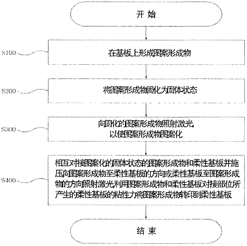
[0096] figure 2 is a flowchart showing the sequence of the pattern transfer method according to the first embodiment of the present invention. figure 2 Among them, in order to pattern the pattern formation 110, when the opening of the pattern is not wide, a positive resist method is used in which the part receiving the laser light is peeled off. In addition, the substrate is, for example, a glass substrate, and the substrate will not be deformed or damaged by heat even if the transfer material is peeled off when irradiated with laser light. This substrate is commonly used in ...


PUM


Abstract

The present invention relates to methods and apparatuses for transferring pattern, a flexible display panel, a flexible solar cell, an electronic book, a thin film transistor, an electromagnetic-shielding sheet, and a flexible printed circuit board applying thereof. A pattern transfer method related to the present invention comprises: a first step of forming a pattern material on a substrate; a second step of hardening the pattern material in the solid state; a third step of patterning the pattern material by irradiating a laser beam to the hardened pattern material in the solid state; and a fourth step of pressing the patterned pattern material in the solid state and a flexible substrate facing each other and transferring the pattern material to the flexible substrate by a viscous force of the flexible substrate occurring in a facing part between the pattern material and the flexible substrate by irradiating the laser beam from the pattern material to the flexible substrate or from the flexible substrate to the pattern material.

Description

technical field [0001] The invention relates to a pattern transfer printing method and a pattern transfer printing device, as well as flexible display panels, flexible solar cells, electronic books, thin film transistors, electromagnetic wave shielding sheets, and flexible printed circuit boards manufactured by the method. Background technique [0002] Recently, in the optoelectronics industry, the display industry, the semiconductor industry, and the bio industry, there is an increasing demand for thinner products and higher performance. In order to meet such demands, it is necessary to form the wiring or functional film layers constituting each component into a smaller and more uniform pattern. [0003] Generally, the existing methods for manufacturing patterns below microns include photolithography, fine mask deposition (Fine Mask Deposition, FMD), printing (printing), nanoimprinting (Nano Imprinting Lithography, NIL), microcontact printing (Micro Contact Printing, MCP),...

Claims


Application Information

Patent Timeline
Patent Type & Authority Applications(China)
IPC IPC(8): B41M5/00B41F16/00
CPCB82Y10/00H05K3/207H01L27/1292H05K3/027H05K3/205G03F7/0002H01L31/022425H05K2203/1545Y02E10/50B82Y40/00H05K2203/107H01L31/0392H05K2203/1173G03F7/34
Inventor 梁民阳康凤哲
Owner KOREA ADVANCED INST OF SCI & TECH
Learn More