
High pulse repetition frequency mode-locking optical fiber laser

A fiber laser, high repetition frequency technology, applied in the direction of lasers, laser components, phonon exciters, etc., can solve the problems of narrow tuning range of SESAMs, affecting saturable absorption, complex production and packaging processes, etc., to achieve small size , simple structure, and high damage threshold

Inactive Publication Date: 2012-06-13
SHANGHAI INST OF OPTICS & FINE MECHANICS CHINESE ACAD OF SCI
View PDF1 Cites 9 Cited by
  • Summary
  • Abstract
  • Description
  • Claims
  • Application Information

AI Technical Summary

Problems solved by technology

[0008] Ultrashort-cavity mode-locked fiber lasers basically use phosphate fiber as the gain medium, and most of the mode-locked devices use semiconductor saturable absorption mirrors (referred to as SESAMs) [see Byun, H., et al., Compact, stable1GHz femtosecond Er-doped fiber lasers.Appl.Opt., 2010.49(29)], however, the tunable range of SESAMs is very narrow, and requires a very complicated production and packaging process, and special attention should be paid to the heat dissipation
A simple and economical alternative is to use single-walled carbon nanotubes (SWCNTs for short) [Yamashita, S., et al., 5-GHz pulsed fiber Fabry-Perot laser mode-locked using carbonnanotubes. Photonics Technology Letters, IEEE , 2005.17(4)], its operating wavelength depends on the diameter of SWCNTs, and the tunable range is narrow; if a large tunable range is to be obtained, SWCNTs with various diameters must be used, which will lead to increased non-saturation loss and damage threshold The decrease, thus affecting its saturable absorption

Method used


Image

  • High pulse repetition frequency mode-locking optical fiber laser
  • High pulse repetition frequency mode-locking optical fiber laser
  • High pulse repetition frequency mode-locking optical fiber laser

Examples


Embodiment Construction

[0028] The present invention will be further described below in conjunction with embodiment, but should not limit protection scope of the present invention with this.

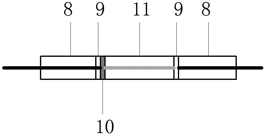
[0029] The structure of the high repetition rate mode-locked fiber laser of the present invention is as follows figure 1 shown. It can be seen from the figure that the high repetition rate mode-locked fiber laser of the present invention includes a pump laser 7 and a laser resonator 2, the laser resonator 2 is an FP cavity structure, and the gain medium 11 and the mode-locking element 10 are located between two optical fibers. Between the end faces of the parts 8, the end faces of the optical fiber connectors are coated with a dichroic film 9, the gain fiber 11 is a phosphate fiber doped with rare earth ions, the mode-locking element 10 is graphene, and the laser resonance One end of the cavity 2 is output through the laser isolator 1, the other end of the laser resonator 2 is connected to an output end of the...


PUM


Abstract

A high pulse repetition frequency mode-locking optical fiber laser comprises a pump laser and a laser resonator, wherein the laser resonator is of an FP (Fabry-Perot) cavity structure. A gain medium and a mode-locking component are positioned between end faces of two optical fiber connectors, a bicolor film is plated on the end face of each optical fiber connector, a gain optical fiber is a phosphate optical fiber doped with rare earth ions, the mode-locking component is grapheme, one end of the laser resonator directly outputs via a laser isolator, the other end of the laser resonator is connected with an output end of a wavelength division multiplexer, an input end of the wavelength division multiplexer is connected with the pump laser, the other output end of the wavelength division multiplexer is connected with the laser isolator to output laser light, and the temperature of the laser resonator is controlled by a temperature control system. The high pulse repetition frequency mode-locking optical fiber laser can generate stable picosecond and even femtosecond without external additional modulation, the repetition frequency is larger than 1GHz ultra-short pulse sequence, and the optical fiber laser is simple in structure and capable of realizing all-fiber integration.

Description

technical field [0001] The invention belongs to laser ultrashort pulse, in particular to a high repetition frequency mode-locked fiber laser. Background technique [0002] High repetition rate (referred to as high repetition rate) ultrashort pulse laser is a key technology for high-speed optical sampling, precise distance measurement, precision laser radar and other scientific research, industry, national defense and military applications. It is a hot issue in the field of laser research. A higher repetition rate means a larger longitudinal mode spacing. The longitudinal modes of each order in the frequency domain of the mode-locked pulse sequence above GHz can be distinguished by the existing filter elements, and it is easy to realize the intensity and phase modulation of the single longitudinal mode to obtain the required waveform, so that it can be applied in high-speed optical communication system, laser-matter interaction, quantum dynamics control and other fields. ...

Claims


Application Information

Patent Timeline
Patent Type & Authority Applications(China)
IPC IPC(8): H01S3/067H01S3/098H01S3/08
Inventor 叶泞泞潘政清叶青蔡海文瞿荣辉
Owner SHANGHAI INST OF OPTICS & FINE MECHANICS CHINESE ACAD OF SCI
Learn More