Unlock instant, AI-driven research and patent intelligence for your innovation.

Carbon dioxide purification system integrated with synthesis gas desulfurization system

A carbon dioxide and desulfurization system technology, applied in liquefaction, inorganic chemistry, chemical industry, etc., can solve the problems of increasing system waste residue discharge, increasing power loss, intermittent regeneration and drying, etc., to reduce consumption, reduce washing amount, compress gas The effect of capacity reduction

Active Publication Date: 2012-06-20
HUANENG CLEAN ENERGY RES INST
View PDF2 Cites 5 Cited by
  • Summary
  • Abstract
  • Description
  • Claims
  • Application Information

AI Technical Summary

Problems solved by technology

[0003] CO in tail gas of chemical synthesis gas desulfurization unit 2 The concentration is relatively high, generally greater than 80%, and it is suitable for conventional low-temperature rectification or pressure swing adsorption process for purification, but this process enters CO 2 The gas flow of the compressor contains nearly 20% non-condensable gas, that is, impurities, which increases the loss of electric energy, and an adsorber needs to be installed for drying and dehydration. In order to ensure that the moisture content of the system is qualified, the adsorber must be intermittently regenerated and dried , which makes the system complex and increases the power consumption of the system, and the molecular sieve adsorbent used also needs to be replaced regularly, which increases the discharge of waste residue in the system

Method used


Image

  • Carbon dioxide purification system integrated with synthesis gas desulfurization system
  • Carbon dioxide purification system integrated with synthesis gas desulfurization system

Examples


Embodiment Construction

[0009] The present invention will be described in further detail below in conjunction with the accompanying drawings.

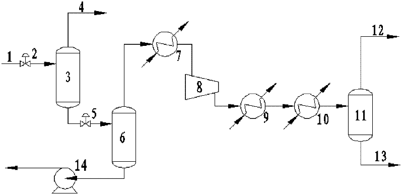
[0010] Referring to the accompanying drawings, a carbon dioxide purification system integrated with a syngas desulfurization system includes a solution non-condensable gas separator 3, and the inlet of the solution non-condensable gas separator 3 passes through a primary pressure-reducing regulating valve 2 and a medium-pressure solution pipeline 1 Connected, the first impurity non-condensable gas discharge pipe 4 at the top of the solution non-condensable gas separator 3 is connected with the flash gas pipeline of the main desulfurization system pipeline, and the liquid outflow pipeline at the bottom of the solution non-condensable gas separator 3 is decompressed by the second stage The regulating valve 5 is connected to the inlet of the solution carbon dioxide gas separator 6, the gas outlet at the top of the solution carbon dioxide gas separator 6 is connec...


PUM


Abstract

A carbon dioxide purification system integrated with a synthesis gas desulfurization system comprises a solution-incondensable gas separator. An inlet of the solution-incondensable gas separator is connected with an intermediate-pressure solution pipe, an impurity incondensable gas discharge pipe at the top of the solution-incondensable gas separator is connected with a main desulfurization system pipe, a liquid outlet pipe at the bottom of the solution-incondensable gas separator is connected with an inlet of a solution-carbon dioxide gas separator, a gas outlet at the top of the solution-carbon dioxide gas separator is connected with an inlet of a carbon dioxide gas-liquid separator through a cold energy recovery heat exchanger, a carbon dioxide compressor, a water cooler in back of the compressor and a quench heat exchanger, an impurity incondensable gas discharge pipe at the top of the carbon dioxide gas-liquid separator is connected with the main desulfurization system pipe, a liquid carbon dioxide discharge pipe at the bottom of the carbon dioxide gas-liquid separator is connected with a storage tank, and a solution discharge pipe at the bottom of the solution-carbon dioxide gas separator is connected with the main desulfurization system pipe through a power pump. The invention can purify and produce liquid carbon dioxide.

Description

technical field [0001] The invention belongs to the technical field of greenhouse gas emission reduction, and in particular relates to a carbon dioxide purification system integrated with a synthesis gas desulfurization system. Background technique [0002] Among the "greenhouse gases" that cause global warming, CO 2 It is one of its main components, and its contribution to the greenhouse effect exceeds the sum of other greenhouse gases. Injection of CO2 products into producing oil fields allows for simultaneous CO2 enhancement of oil recovery (EOR) 2 Sealing, from "being harmed by the sky" to "being treasured by the earth", realizing CO2 while obtaining certain economic benefits 2 emissions reduction; also for enhanced coal bed methane mining (ECBM), carbonated beverages, CO 2 Gas shielded welding, dry ice making, tobacco puffing, cement making, converter steelmaking and degradable plastics making, etc. [0003] CO in tail gas of chemical synthesis gas desulfurization u...

Claims


Application Information

Patent Timeline
Patent Type & Authority Applications(China)
IPC IPC(8): C01B31/20F25J3/08C01B32/50
CPCY02P20/10
Inventor 郜时旺牛红伟许世森蔡铭刘练波
Owner HUANENG CLEAN ENERGY RES INST
Features
  • R&D
  • Intellectual Property
  • Life Sciences
  • Materials
  • Tech Scout
  • Unparalleled Data Quality
  • Higher Quality Content
  • 60% Fewer Hallucinations
Learn More