Waste heat recovering device for conduction oil furnace

A technology of waste heat recovery device and heat conduction oil furnace, which is applied to fluid heaters, lighting and heating equipment, etc., can solve the problems of not meeting the requirements of energy saving and environmental protection, and low thermal efficiency of boilers, and achieve flexible and convenient layout, high waste heat recovery rate, well-designed effects

Inactive Publication Date: 2012-07-04
NANJING RECLAIMER ENVIRONMENTAL TEKNIK
View PDF8 Cites 11 Cited by
  • Summary
  • Abstract
  • Description
  • Claims
  • Application Information

AI Technical Summary

Problems solved by technology

[0005] However, if the unit using the heat-conducting oil furnace does not need the steam generated by the waste heat recovery process, the use of this type of technology will be greatly restricted, and only the air preheater can be added to recover part of the waste heat of the flue gas. In order to avoid the waste heat of the air preheater Low-temperature corrosion, the exhaust gas temperature of the boiler is usually above 160°C, and the overall thermal efficiency of the boiler is still low, which does not meet the requirements of energy saving and environmental protection

Method used


Image

  • Waste heat recovering device for conduction oil furnace
  • Waste heat recovering device for conduction oil furnace
  • Waste heat recovering device for conduction oil furnace

Examples


Embodiment 1

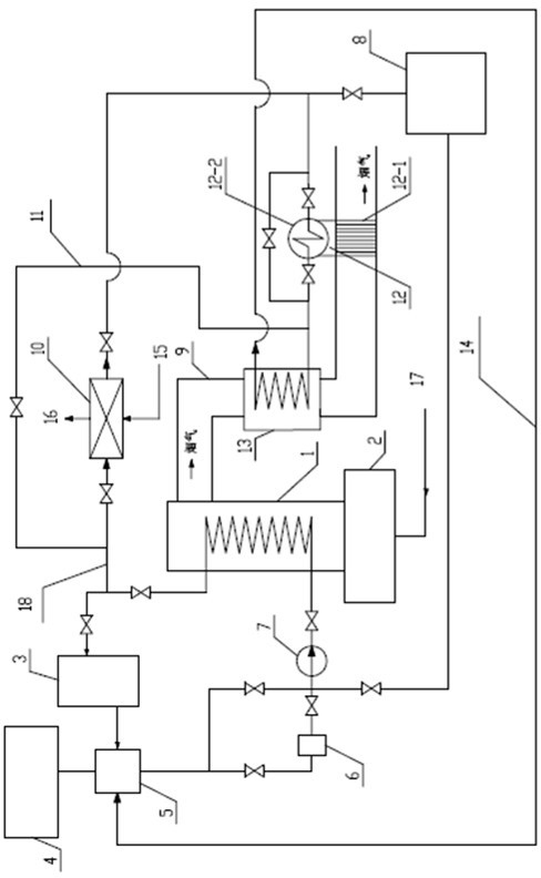
[0035] attached image 3 It is a schematic flow chart of an embodiment of the structure of the heat-conducting oil furnace tail gas waste heat recovery device of the present invention, wherein the heat-conducting oil furnace includes a furnace body 1, a heating source 2, a flue 9 and a high-temperature end heat-conducting oil circulation circuit, and the heating source 2 can be coal or oil. or gas as fuel. The heat transfer oil circulation loop at the high temperature end includes heat-using equipment 3, oil-gas separator 5, filter 6, hot oil pump 7, high-level expansion tank 4, low-level oil storage tank 8, and supporting pipelines, valves and control instruments, etc. The heat transfer oil circulation loop at the high temperature end of the present invention is as follows: the heat transfer oil enters the furnace body 1 after being pressurized by the heat oil pump 7 to absorb the heat generated by combustion, and then enters the heat oil pump after passing through the heat u...

Embodiment 2

[0043] Another embodiment of the present invention is: the outlet of the heat transfer oil internal circulation pipeline 18 is between the outlet of the heat oil pump 7 and the oil inlet pipeline of the furnace body 1, and the rest of the implementation is the same as that of Embodiment 1.


PUM


Abstract

The invention relates to a waste heat recovering device for a conduction oil furnace. The conduction oil furnace includes a furnace body, a heating source, a high-temperature end conduction oil circulation loop and a flue; the waste heat recovering device includes an inner circulating pipeline, a thermoregulator, a phase change heat exchanger and a coal economizer; the phase change heat exchangerincludes an evaporator and a condenser that are connected through a pipeline to form a phase change working medium circulation loop; the evaporator and the coal economizer are arranged in the flue; the condenser is arranged outside the flue; a conduction oil inlet end or a conduction oil outlet end of the furnace body is sequentially connected with the thermoregulator, the condenser and a conduction oil inlet end of the coal economizer through the inner circulating pipeline; and a conduction oil outlet end of the coal economizer is connected to the high-temperature end conduction oil circulation loop. According to the invention, the conduction oil furnace can economically operate with high heat efficiency, the problem that the waste heat of the conduction oil furnace is difficult to recover is solved, and the purposes of energy saving and consumption reducing are achieved.

Description

technical field [0001] The invention relates to a heat-conducting oil furnace tail gas waste heat recovery device, which belongs to the field of boiler flue gas waste heat recovery. Background technique [0002] The heat transfer oil furnace is a special boiler that uses an organic heat carrier, namely heat transfer oil, as the working medium. The heat transfer oil is heated by the high-temperature flue gas generated by fuel combustion. When the flue gas produced after combustion is discharged through the chimney, the temperature is generally around 170°C, and some are as high as 300°C, which not only wastes heat, but also causes thermal pollution to the environment. [0003] Most heat-conducting oil furnaces do not recover waste heat or only increase the air preheater to recover part of the waste heat of flue gas. Part of the process is equipped with a waste heat recovery device with a steam generator such as a heat pipe boiler. For example, ZL200420027889.4 provides a hea...

Claims


Application Information

Patent Timeline
Patent Type & Authority Applications(China)
IPC IPC(8): F24H9/00
Inventor 王海波丁鑫张业富邢迎明
Owner NANJING RECLAIMER ENVIRONMENTAL TEKNIK
Why Eureka
Try Eureka