
Nano-electromechanical resonant sensor based on graphene sheet layer and manufacturing method thereof

A resonant sensor, graphene sheet technology, applied in piezoelectric devices/electrostrictive devices, processes for producing decorative surface effects, piezoelectric/electrostrictive/magnetostrictive devices, etc. Low-pass filtering of olefin resonators, unfavorable large-scale, mass production, complex optical path design, etc., achieve the effect of small quality, elimination of low-pass filtering phenomenon, and strong controllability

Active Publication Date: 2012-07-04
江苏泛在智能电气有限公司
View PDF5 Cites 17 Cited by
  • Summary
  • Abstract
  • Description
  • Claims
  • Application Information

AI Technical Summary

Problems solved by technology

Documentation [Bunch JS, et al . Electromechanical resonators from graphene sheets, Science, 2007 , 315:490] The graphene sheet resonator was studied by the method of optical excitation and optical lever detection, but the design of the optical path of this method is complicated, and it is difficult to be popularized in practical applications
Literature [Chen C, et al. Performance of monolayer grapheme nanomechanical resonators with electrical readout. Nature Nanotechnology, 2009, 4, 861-867] mentioned graphene sheet resonator has low-pass filtering phenomenon, and the external circuit needs to be mixed in the test, and the circuit is complicated
In addition, suspended graphene sheets are basically obtained by mechanical exfoliation, which has low yield and high randomness, which is not conducive to large-scale and batch production

Method used


Image

  • Nano-electromechanical resonant sensor based on graphene sheet layer and manufacturing method thereof
  • Nano-electromechanical resonant sensor based on graphene sheet layer and manufacturing method thereof
  • Nano-electromechanical resonant sensor based on graphene sheet layer and manufacturing method thereof

Examples


Embodiment Construction

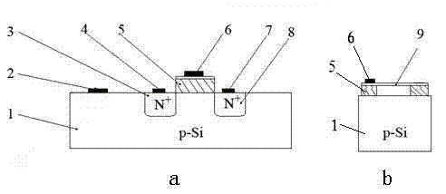
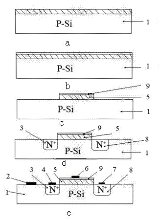
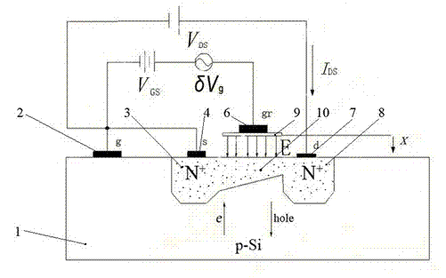
[0013] The structure of the nanoelectromechanical resonant sensor based on the graphene sheet in the present invention is as follows: figure 1 shown. A P-type silicon wafer with a low impurity concentration is used as a substrate, that is, a P-Si substrate 1, and two N + Regions, namely the drain-N type doped region 3 and the source-N type doped region 8, are on the surface of the P-Si substrate 1, and are located in the drain-N type doped region 3 and the source-N type In the middle of the doped region 8, two SiO 2 Anchor region 5, in two SiO 2 On the anchor area 5 is a graphene two-ends-fixed beam 9, and the two ends of the graphene-two-ends-fixed beam 9 are respectively suspended from two SiO 2 On the anchor region 5 , a top gate electrode 6 connected to the graphene double-end fixed beam 9 is arranged on one end of the graphene double-terminal fixed beam 9 . The drain electrode 4 and the source electrode 7 are located on the drain-N type doped region 3 and the source-...


PUM


Abstract

The invention discloses a nano-electromechanical resonant sensor based on a graphene sheet layer and a manufacturing method thereof. A P-Si substrate is provided with a drain-N type doping region and a source-N type doping region; the drain-N type doping region is provided with a drain electrode; the source-N type doping region is provided with a source electrode; two SiO2 anchor regions are arranged between the drain-N type doping region and the source-N type doping region on the surface of the P-Si substrate; two ends of the graphene for fixing support beams are respectively suspended on the two SiO2 anchor regions; and one of the two ends of the graphene for fixing the support beams is provided with a top gate electrode connected with the graphene. The resonant frequency of a resonator is determined by using the change of an electric field caused by beam vibration, and a weak resonant signal can be directly amplified into a voltage signal capable of being used for detection, so that an external active circuit is avoided, the circuit is simplified, and the low-pass filter phenomenon caused by parasitic capacitance can be eliminated; and therefore, the nano-electromechanical resonant sensor is in particular suitable for detection of chemical substances with ultra-small masses.

Description

technical field [0001] The invention belongs to the application field of nano-electromechanical systems (NEMS), in particular to a nano-electromechanical resonant sensor for ultra-small mass detection and a manufacturing method thereof. Background technique [0002] For a mechatronic resonator, the natural frequency of the system ( ) Influence coefficient with stiffness k increases with the increase of the effective mass m eff decrease and increase. The method of increasing the resonance frequency is mainly by reducing the mass of the system and increasing the elastic stiffness, and the elastic stiffness is related to the Young's modulus of the beam E Proportional. Graphene is a material with a two-dimensional structure discovered so far, its single layer thickness is only 0.35 nm, Young's modulus , effective mass m eff Extremely small, in line with the requirements of increasing the resonance frequency. [0003] The existing nano-electromechanical resonant sensor...

Claims


Application Information

Patent Timeline
IPC IPC(8): G01H11/06G01N27/00B81B3/00B81C1/00
Inventor 王权张进胡然邵盈杨晓丹张艳敏
Owner 江苏泛在智能电气有限公司
Learn More