
Measuring device for 1400 DEG C high-temperature modal test of wing helm structure of hypersonic aircraft

A hypersonic, structural testing technology, used in measuring devices, machine/structural component testing, vibration testing, etc., can solve problems such as strength and stiffness reduction, softening and softening of metal connectors at high temperature, and achieve convenient manufacturing and installation. The effect of maintaining the strength and rigidity, and the simple structure of the device

Inactive Publication Date: 2012-07-04
BEIHANG UNIV
View PDF4 Cites 23 Cited by
  • Summary
  • Abstract
  • Description
  • Claims
  • Application Information

AI Technical Summary

Problems solved by technology

Under normal circumstances, when the temperature is higher than 600°C-700°C, even if high-temperature resistant metal materials such as high-temperature alloys or titanium alloys are used, there will be softening, increased deformation, and decreased strength and stiffness, such as the melting point of copper The melting point of No. 45 steel is 1350 °C, and the measurement acceleration sensor and force transmission metal joints in the extreme high temperature environment of 1400 °C will not only soften at high temperature, but even be melted and fail.
However, there is no relevant research report on the thermal modal test at such a high temperature (1400°C).

Method used


Image

  • Measuring device for 1400 DEG C high-temperature modal test of wing helm structure of hypersonic aircraft
  • Measuring device for 1400 DEG C high-temperature modal test of wing helm structure of hypersonic aircraft
  • Measuring device for 1400 DEG C high-temperature modal test of wing helm structure of hypersonic aircraft

Examples


Embodiment Construction

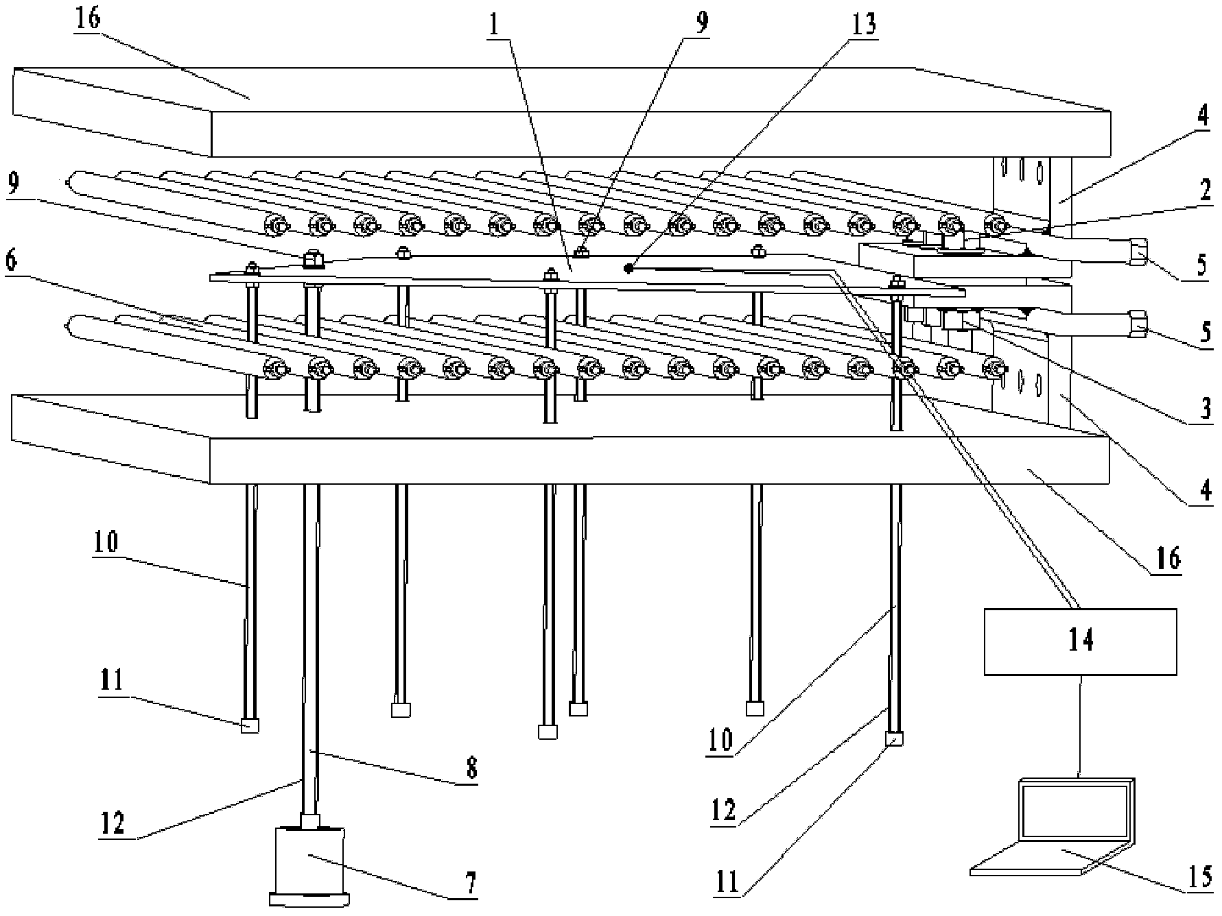
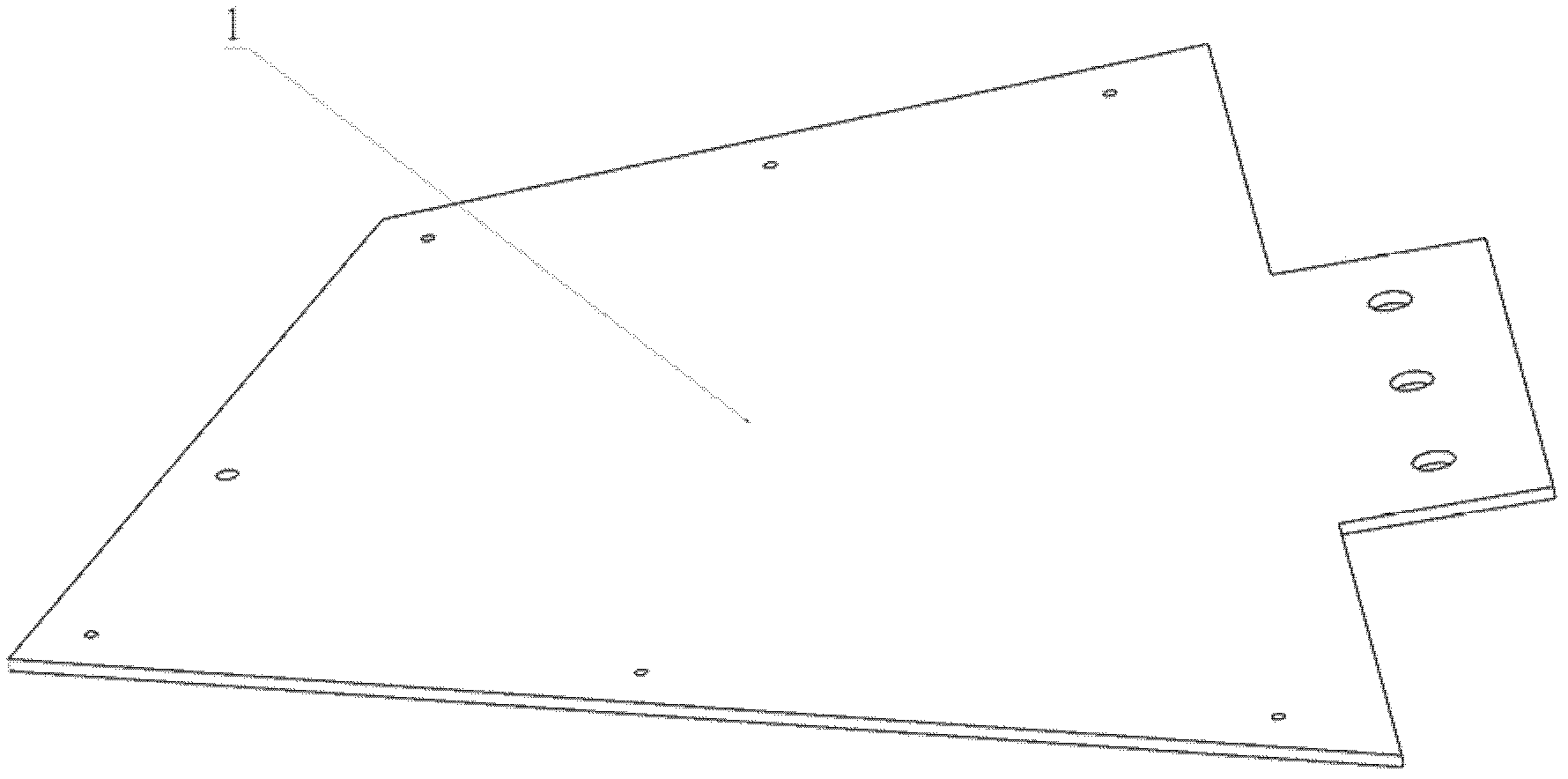
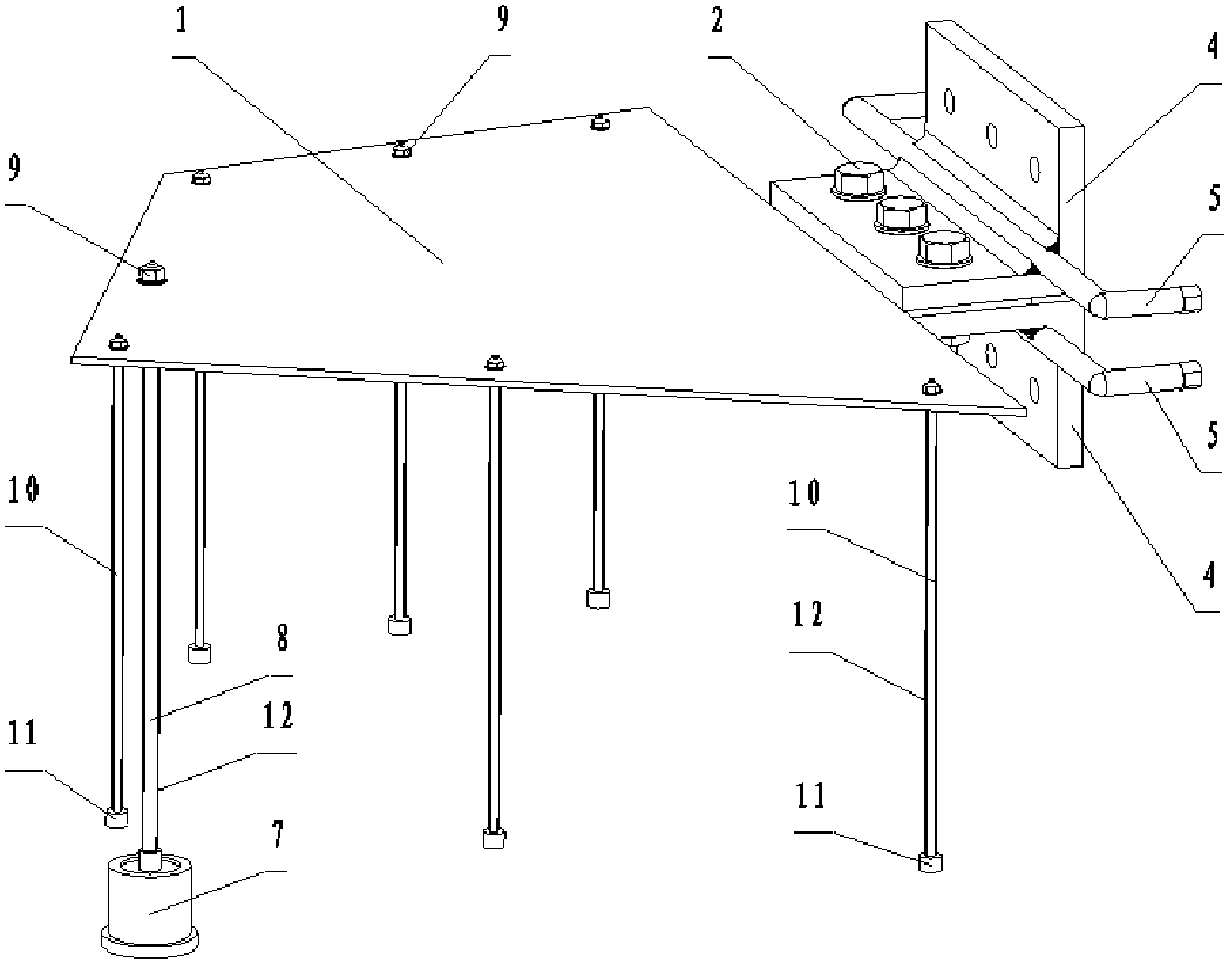
[0024] Such as figure 1 , figure 2 and image 3 As shown, the present invention consists of a hypersonic aircraft wing rudder structure test piece 1, a high-temperature steel bolt 2, a high-temperature steel nut 3, an L-shaped fixed bracket 4, a water-cooling cooling pipeline 5, a silicon carbon infrared radiation array 6, and an excitation source 7 , molybdenum dowel rod 8, molybdenum locking nut 9, molybdenum rod guide rod 10, acceleration sensor 11, high temperature reflective coating 12, platinum rhodium thermocouple sensor 13, signal amplifier 14, computer 15 and high temperature ceramic heat shield 16 composition.

[0025] The hypersonic aircraft wing rudder structure test piece 1 is fixed on the L-shaped fixing bracket 4 by high-temperature steel bolts 2 and high-temperature steel nuts 3 to form a cantilever structure. The corners of a pair of L-shaped fixed brackets 4 are respectively welded with a steel water-cooled cooling pipeline 5, and the L-shaped fixed brack...


PUM

PropertyMeasurementUnit
Melting pointaaaaaaaaaa

Abstract

The invention relates to a measuring device for a 1400 DEG C high-temperature modal test of a wing helm structure of a hypersonic aircraft. The measuring device comprises a test piece of the wing helm structure of the hypersonic aircraft, an L-shaped fixed bracket, a water-cooling pipeline, a silicon carbon infrared radiation array, an excitation source, a molybdenum force transfer rod, a molybdenum-rod guide bar, an acceleration sensor, a dual platinum rhodium thermocouple sensor, a computer and a high-temperature ceramic heat-insulating plate. When the test for the wing helm structure of the hypersonic aircraft is performed, the wing helm structure is heated by the silicon carbon infrared radiation array, and meanwhile, the excitation source is randomly vibrated, thereby forming an environment of a high-temperature thermal vibrating coupling test. The metal molybdenum-rod guide bar is directly mounted on the wing helm structure of the hypersonic aircraft; a vibrating signal of the wing helm structure of the hypersonic aircraft is transferred to a place beyond a 1400 DEG C high-temperature thermal field; a normal-temperature acceleration sensor is mounted at a cold end of the molybdenum-rod guide bar, so as to dynamically measure a thermal modal signal of the wing helm structure introduced into a normal temperature area; and the invention provides an effective dynamical high-temperature thermal modal test means for developing a hypersonic remote strategic aircraft.

Description

technical field [0001] The invention relates to a 1400°C high-temperature modal test measuring device for a hypersonic aircraft wing rudder structure, especially in the aerothermal simulation test of a hypersonic aircraft structure, which can measure the high temperature of a composite material wing rudder structure when it vibrates in a thermal environment as high as 1400 °C The dynamic change law of the mode provides an important experimental basis for the safety and reliability design of the wing rudder structure of hypersonic aircraft such as high-speed missiles and long-range strategic mobile strike weapons in high-speed, high-temperature thermal-vibration coupling environments. Background technique [0002] With the development of aerospace technology, the design flight speed of long-range maneuvering aircraft is constantly increasing. At the same time, modern warfare requires high-speed, high-precision, and high-mobility combat performance of aircraft, which has cause...

Claims


Application Information

Patent Timeline
IPC IPC(8): G01M7/02
Inventor 吴大方潘兵王岳武孙冰郑力铭
Owner BEIHANG UNIV
Learn More