Flue gas decarbonization system and flue gas decarbonization method for two-step regeneration of carbon dioxide

A carbon dioxide and flue gas technology, applied in chemical instruments and methods, separation methods, inorganic chemistry, etc., can solve problems such as failure to effectively achieve energy saving, low cost, high cost of metal oxides, and complex adsorbent processes, etc. Process integration studies promote, improve energy efficiency, and save sensible and evaporative heat

Active Publication Date: 2012-07-18
XI AN JIAOTONG UNIV
View PDF2 Cites 1 Cited by
  • Summary
  • Abstract
  • Description
  • Claims
  • Application Information

AI Technical Summary

Problems solved by technology

The disadvantage is that according to the experimental results at this stage, the process of preparing the adsorbent is complicated, the cost of the metal oxide used is high, and the efficiency of the adsorbent in adsorbing carbon dioxide is about 20% to 30% lower than that of the chemical absorption method.
[0009] Due to the above defects, the existing power plant flue gas purification systems still have a lot of room for development in terms of system design, energy saving, and environmental protection, and have not yet been able to effectively achieve the goals of energy saving and low cost.

Method used


Image

  • Flue gas decarbonization system and flue gas decarbonization method for two-step regeneration of carbon dioxide
  • Flue gas decarbonization system and flue gas decarbonization method for two-step regeneration of carbon dioxide

Examples


Embodiment Construction

[0034] The present invention will be further described in detail below in conjunction with specific embodiments, which are explanations of the present invention rather than limitations.

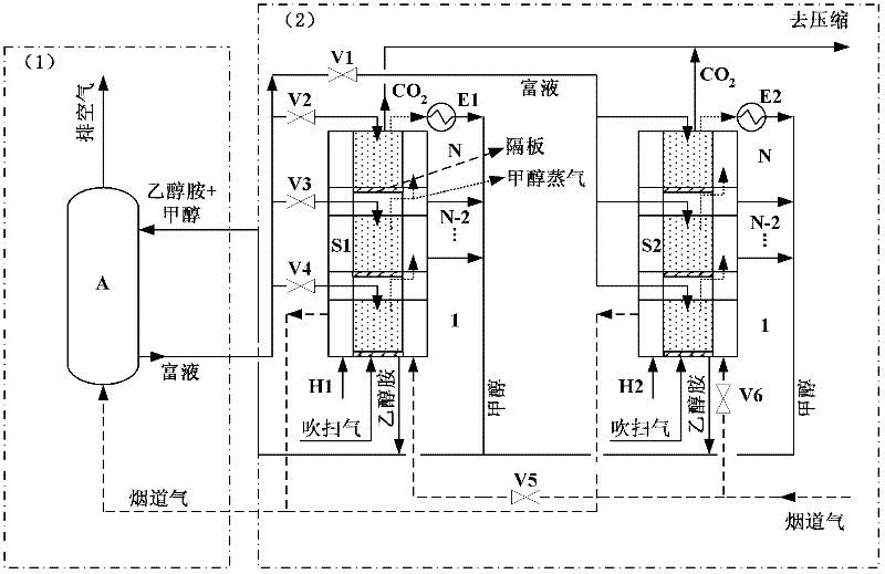
[0035] see figure 1 , a flue gas decarbonization system for carbon dioxide two-step regeneration, including an absorption tower with a flue gas inlet at the bottom and a regeneration tower with an N-level packed tower structure, and an alcohol amine-methanol mixture for absorbing carbon dioxide is installed in the absorption tower Solvent, the flue gas enters the absorption tower after the first heat transfer of the regeneration tower, absorbs carbon dioxide through the alcohol amine-methanol mixed solvent, and then discharges from the top outlet;

[0036] The alcohol amine-methanol mixed solvent absorbs carbon dioxide and then splits into the first to N stages of the regeneration tower. The first stage of the regeneration tower at the bottom is equipped with a heat exchange pipeline for flue...


PUM


Abstract

The invention discloses a flue gas decarbonization system and a flue gas decarbonization method for two-step regeneration of carbon dioxide. The flue gas decarbonization system is formed by coupling an alkylol amine and methanol mixed solution adsorption system with a two-step carbon dioxide regeneration system, wherein when the two-step carbon dioxide regeneration system works, two steps of removing methanol before regeneration and regenerating alkylol amine carbonate are carried out. In the step of removing methanol before regeneration, flue gas waste heat is utilized to provide a heat source to remove the methanol in rich liquor after adsorption; the regeneration process only aims at the alkylol amine carbonate; the energy consumption of sensible heat and evaporation heat are avoided; and the steam consumption of the thermal regeneration process is reduced. Two regeneration towers alternately implement removal of the methanol and regeneration of the alkylol amine carbonate by two sets of valve equipment, so that the continuous operation of a trapping system is ensured. According to the invention, both the flue gas waste heat and the condensation heat of methanol steam are utilized, the temperature of the regenerated carbon dioxide is reduced, the flue gas decarbonization of a power plant is efficiently implemented, and the flue gas decarbonization system and the flue gas decarbonization method for two-step regeneration of carbon dioxide have the characteristics of cleanness, high efficiency, energy saving, high decarbonization rate and the like.

Description

technical field [0001] The invention belongs to the technical field of carbon dioxide emission reduction in flue gas, and relates to a flue gas decarbonization system with two-step regeneration of carbon dioxide and a method thereof. Background technique [0002] With the rapid development of the global economy, the demand for energy consumption has become prominent, and the resulting environmental problems such as the greenhouse effect are posing great challenges to the sustainable development of human beings. Carrying out basic and applied research on efficient flue gas purification technology from concentrated emission sources is of great practical significance for effectively reducing carbon dioxide emissions into the atmosphere, protecting the living environment of human beings, and promoting sustainable development. Reducing CO2 emissions from concentrated emission point sources such as power plants is the most effective way to reduce emissions. [0003] At present, t...

Claims


Application Information

Patent Timeline
Patent Type & Authority Applications(China)
IPC IPC(8): B01D53/14B01D53/18C01B31/20C01B32/50
CPCY02C10/06Y02A50/20Y02C20/40Y02P20/129Y02P20/151
Inventor 张早校余云松李云董锐锋马登龙卢红芳
Owner XI AN JIAOTONG UNIV
Why Eureka
Try Eureka