

Iron-carbon micro-electrolysis reaction system of multistage fluidized bed
An iron-carbon micro-electrolysis and reaction system technology, applied in chemical instruments and methods, water/sewage treatment, water/sludge/sewage treatment, etc., can solve problems such as increasing the difficulty of reactor maintenance, aggravating hardening, and increasing treatment costs. , to optimize the micro-electrolysis effect, improve the reaction environment, and avoid the effect of hardening
- Summary
- Abstract
- Description
- Claims
- Application Information
AI Technical Summary
Problems solved by technology
Method used
Image

Examples
Embodiment Construction
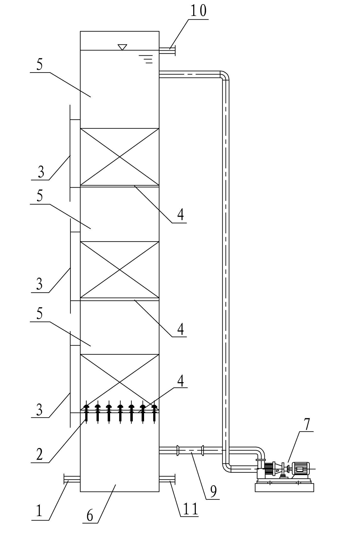
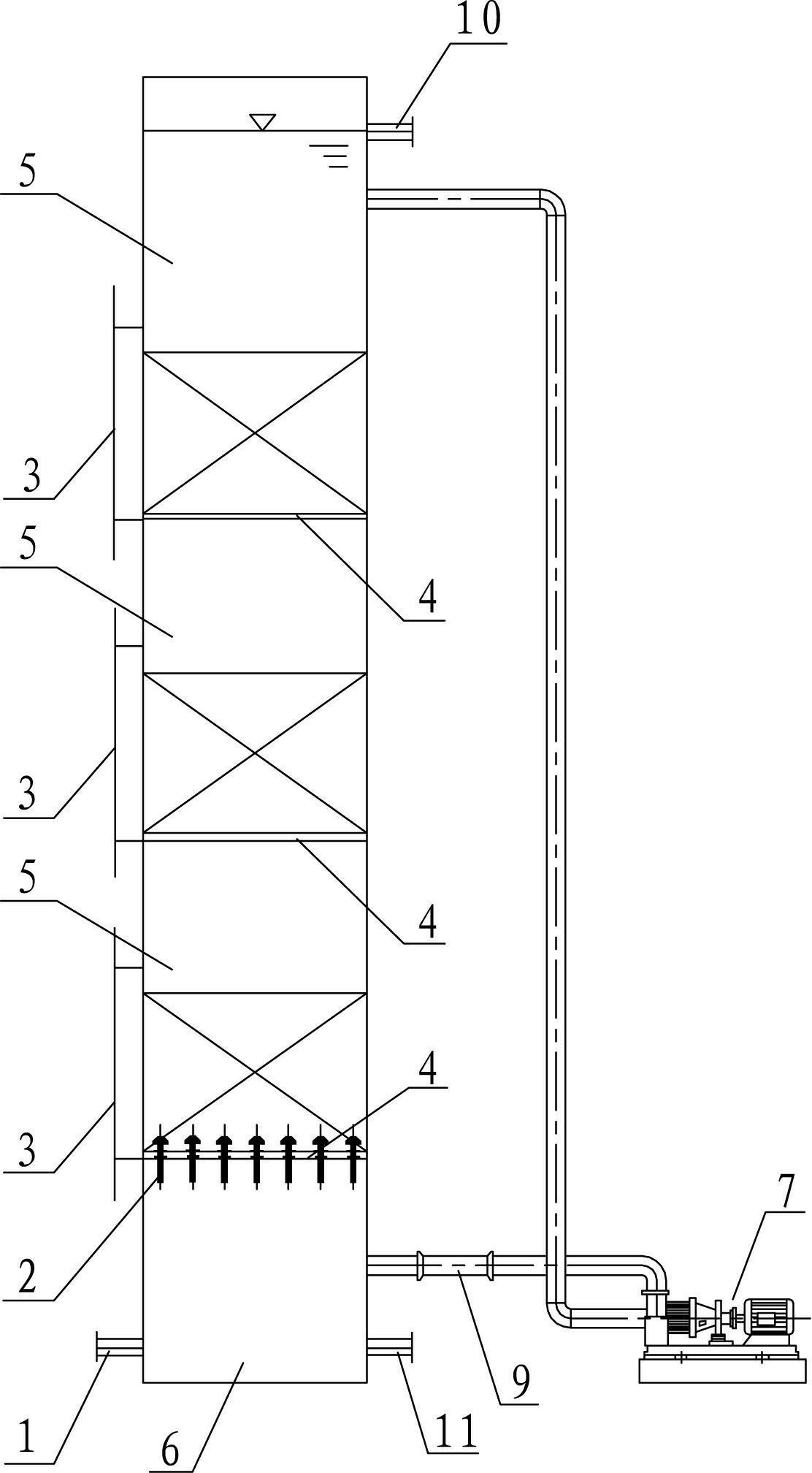
[0020] refer to figure 1 , multi-stage fluidized bed iron-carbon micro-electrolysis reaction system, comprising a reactor, the lower part of the reactor is provided with a water distribution chamber 6 with a lower circulating nozzle, the upper part of the reactor is provided with an upper circulating nozzle, the lower circulating nozzle, the upper circulating nozzle They are communicated with each other through a pipeline, and the pipeline is provided with an internal circulation pump 7, and the upper space in the reactor is divided into a plurality of reaction chambers 5 stacked from bottom to top by several screen partitions 4, and the reaction chamber 5 is located in the water distribution chamber. Room 6 above. Specifically, the sieve diameter of the screen partition 4 is 0.5mm-1mm, and this aperture will effectively ensure that the partition can support the packing while allowing the upward flow to pass through.
[0021] As a further preferred embodiment, a jet aerator 9...
PUM
 Abstract
Description
Claims
Application Information