Power generation system using exhausting and cooling waste heat in internal combustion engine at the same time and control method therefor

A technology of power generation system and internal combustion engine, which is applied in the control of coolant flow, cooling of engine, internal combustion piston engine, etc., can solve the problems of incapable of practical application, inability to make full use of internal combustion engine, large volume of refrigeration device, etc., and achieve saving The effect of consumption rate, high useful work output, and little damage to the environment

Inactive Publication Date: 2012-08-01
BEIJING UNIV OF TECH
View PDF5 Cites 49 Cited by
  • Summary
  • Abstract
  • Description
  • Claims
  • Application Information

AI Technical Summary

Problems solved by technology

Using waste heat for heating can make good use of the waste heat of the engine in winter, but it cannot make full use of the waste heat of the internal combustion engine when heating is not needed in other seasons
The use of temperature difference power generation technology is limited by low conversion efficiency, and it is still not possible to realize practical applications.
Refrigeration devices using adsorption heat pumps are often too bulky, inefficient, and not suitable for automotive internal combustion engine applic

Method used


Image

  • Power generation system using exhausting and cooling waste heat in internal combustion engine at the same time and control method therefor
  • Power generation system using exhausting and cooling waste heat in internal combustion engine at the same time and control method therefor
  • Power generation system using exhausting and cooling waste heat in internal combustion engine at the same time and control method therefor

Examples


Example Embodiment

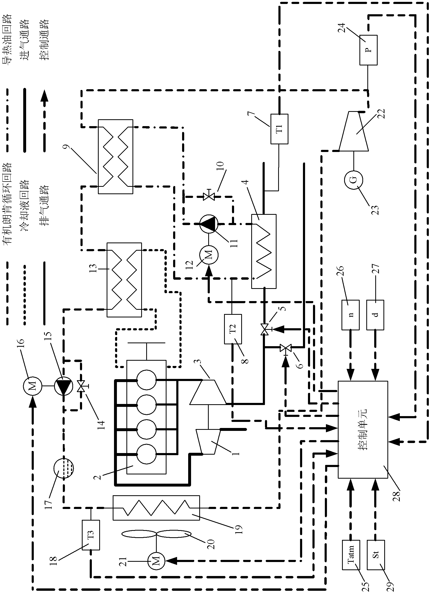
[0032] The present invention will be further described in detail below in conjunction with the accompanying drawings.

[0033] An organic Rankine cycle power generation system utilizing the exhaust heat of an internal combustion engine and cooling waste heat at the same time of the present invention, its connection diagram is as follows figure 1 As shown, including the heat transfer oil circuit, the organic Rankine cycle circuit and the control passage. The components included in the above-mentioned heat transfer oil circuit for absorbing the exhaust heat of the internal combustion engine are: working fluid pump 11, regulating motor 12, pressure regulating valve 10, exhaust heat exchanger 4 and evaporator 9, exhaust normally open switch valve 5, Exhaust normally closed on-off valve 6 and piping connecting them. The components included in the above-mentioned organic Rankine cycle loop for recovering the residual heat of the internal combustion engine coolant and the heat trans...


PUM


Abstract

The invention discloses a power generation system using exhausting and cooling waste heat in an internal combustion engine at the same time and a control method therefor. The control method comprises the steps as follows: transferring waste heat in the cooling liquid of the internal combustion engine to an organic working medium by using a preheater in an organic Rankine cycle loop; transferring waste heat taken away by the exhaust gas of the internal combustion engine to the working medium of the organic Rankine cycle loop by using a heat-conducting oil loop; evaporating and gasifying the working medium; transforming enthalpy change in a high-enthalpy expansion process into useful work for outputting by using a single-screw expansion machine; driving a power generator to generate power; taking the tail gas temperature of an exhaust pipe outlet as feedback quantity for realizing the flow closed-loop control of the heat-conducting oil; taking the inlet working medium temperature of the single-screw expansion machine as feedback quantity for realizing the flow closed-loop control of the organic working medium; and taking the outlet working medium temperature of a condenser as feedback quantity for realizing the closed-loop control of the fan motor of the condenser. According to the invention, the flow quantities of the working mediums of the organic Rankine cycle loop and the heat-conducting oil loop are adjusted by using the segmented PI (Proportion Integration) control, so that the waste heat in the internal combustion engine is made the best of, the heat efficiency of the internal combustion engine is improved, and the hazard of the exhaust gas on the environment is reduced.

Description

technical field [0001] The invention belongs to the technical field of waste heat recovery, and relates to an organic Rankine cycle power generation system and a control method for simultaneously utilizing exhaust gas of an internal combustion engine and cooling waste heat. The system uses the preheater in the organic Rankine cycle to transfer the waste heat of the internal combustion engine coolant to the organic working medium, and uses the heat transfer oil circuit to transfer the exhaust heat of the internal combustion engine to the working medium in the evaporator of the organic Rankine cycle. The single-screw expander outputs useful work to drive the generator to generate electricity, and the designed closed-loop control system adjusts the thermal cycle working status of the heat transfer oil circuit and the organic Rankine cycle circuit according to the working status of the internal combustion engine. Background technique [0002] At present, only a small part of the...

Claims


Application Information

Patent Timeline
IPC IPC(8): F02G5/04F01K25/10F01K13/02F01P7/04F01C13/00
CPCY02T10/166Y02E20/14Y02T10/12
Inventor 张红光王恩华范伯元杨凯
Owner BEIJING UNIV OF TECH
Why Eureka
Try Eureka