
Clock generating method and clock generating circuit for CMOS (complementary metal oxide semiconductor) without crystal oscillator

A technology of clock generation circuit and crystal oscillator, which is applied in the field of CMOS clock generation without crystal oscillator and CMOS clock generation circuit without crystal oscillator, can solve the problems of incompatibility, incompatibility and high production cost of CMOS technology, so as to improve integration and stability, reduce Achieve cost and power consumption, and avoid circuit damage

Inactive Publication Date: 2012-08-15
ANHUI UNIVERSITY
View PDF4 Cites 13 Cited by
  • Summary
  • Abstract
  • Description
  • Claims
  • Application Information

AI Technical Summary

Problems solved by technology

[0010] The inventor found in the process of realizing the present invention that: the above-mentioned method 1 has the problems of off-chip implementation and high power consumption; specifically, with the development of large-scale integrated circuit technology, the integration degree of the chip is getting higher and higher, and the area of ​​the chip is getting higher and higher. The smaller the crystal oscillator is, the off-chip implementation is usually used; however, the off-chip implementation will affect the area, cost and reliability of the system; in addition, the power consumption of the crystal oscillator and its additional circuits is not low, thus becoming a low-power consumption product. development bottleneck
The MEMS technology in the above method 2 is not compatible with the current mainstream integrated circuit CMOS technology, and there are problems such as high production cost and limited application range.
Although the above method 3 can use IC technology, but because the piezoelectric film needs some special materials such as AIN and ZnO to be made, it is not compatible with the standard CMOS process; in addition, the film bulk acoustic resonator and bulk acoustic wave piezoelectric Like resonators, although it can be embedded in the package of the chip, it is difficult to achieve a true full integration of the system

Method used


Image

  • Clock generating method and clock generating circuit for CMOS (complementary metal oxide semiconductor) without crystal oscillator
  • Clock generating method and clock generating circuit for CMOS (complementary metal oxide semiconductor) without crystal oscillator
  • Clock generating method and clock generating circuit for CMOS (complementary metal oxide semiconductor) without crystal oscillator

Examples


Embodiment 1

[0036] Embodiment 1. A method for generating a CMOS clock without a crystal oscillator.

[0037] The method of this embodiment is a method for generating a high-precision clock signal on the basis of a digitally controlled oscillator. It should be noted that "no crystal oscillator" in the present invention means that the electronic equipment that requires a clock signal does not need to use a crystal oscillator during normal use (such as after leaving the factory), that is, the clock signal of the electronic equipment is not provided by the crystal oscillator; It is only used when setting the frequency locking control information of the variable capacitor array in the numerical control oscillator, such as the crystal oscillator is only used before the electronic equipment leaves the factory or when the electronic equipment is repaired.

[0038] The method of this embodiment specifically includes:

[0039] First, a numerically controlled oscillator generates a high-frequency s...

Embodiment 2

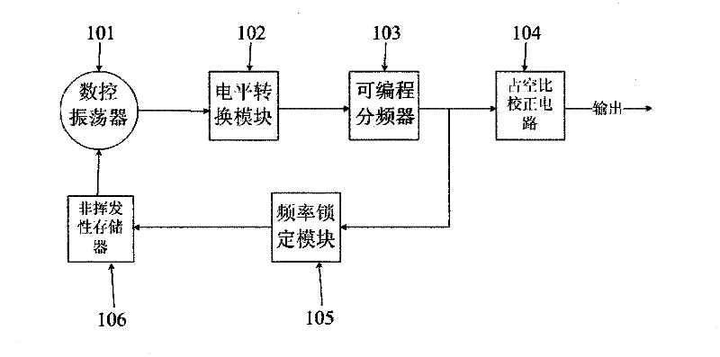
[0044] Embodiment 2: CMOS clock generation circuit without crystal oscillator. The structure of the circuit is attached as figure 2 shown.

[0045] figure 2 The CMOS clock generation circuit without a crystal oscillator in the system includes: a digitally controlled oscillator 101 , a level conversion module 102 , a programmable frequency divider 103 , a duty ratio correction circuit 104 , a frequency locking module 105 and a non-volatile memory 106 . Wherein, the digitally controlled oscillator 101 is connected to the level shifting module 102 and the non-volatile memory 106 respectively, the programmable frequency divider 103 is connected to the level shifting module 102, the duty cycle correction circuit 104 and the frequency locking module 105 respectively, and the non-volatile The permanent memory 106 is connected with the frequency locking module 105.

[0046] The digitally controlled oscillator 101 is mainly used to generate a high-frequency sinusoidal oscillation ...


PUM


Abstract

The invention relates to a clock generating method and a clock generating circuit for a CMOS (complementary metal oxide semiconductor) without a crystal oscillator. The clock generating method includes: generating high-frequency sine oscillation signals by a digital-control oscillator; converting the high-frequency sine oscillation signals into square-wave signals output in single-end mode; underclocking the square-wave signals to obtain clock signals of preset frequency according to preset fractional frequency; regulating duty ratio of the clock signals so that the duty ratio of the clock signals can meet the requirement of preset duty ratio of clock, and outputting the clock signals, wherein a variable capacitor array in the digital-control oscillator is controlled by frequency locking control information. A method for setting the frequency locking control information includes: generating frequency control information according to frequency difference between output signals of an external crystal oscillator and the clock signals underclocked. By the clock generating method, the clock generating circuit can be smaller in size and lower in power consumption, low-cost CMOS technology can be realized in chips, and accordingly, integrity and stability of the system are improved, system realizing cost and power consumption are reduced.

Description

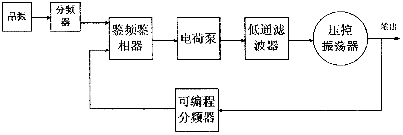
technical field [0001] The invention relates to clock generation technology, in particular to a crystal-less CMOS clock generation method and a crystal-less CMOS clock generation circuit. Background technique [0002] The clock signal is very important for many electronic products, and various components in the electronic product can work together under the action of the clock signal. [0003] Currently, clock generation methods mainly include the following three types: [0004] Method 1: A clock signal is generated by using a phase locked loop (Phase Lock Loop, PLL) frequency synthesizer. A specific example of a PLL frequency synthesizer is figure 1 shown. [0005] figure 1 The phase-locked loop frequency synthesizer mainly includes: crystal oscillator, frequency divider (including figure 1 programmable frequency divider), frequency and phase detectors, charge pumps, low-pass filters, and voltage-controlled oscillators. A phase frequency detector compares the phases o...

Claims


Application Information

Patent Timeline
IPC IPC(8): H03K3/02H03L7/18H03L7/099
Inventor 吴秀龙蔺智挺柏娜陈军宁孟坚徐太龙李正平谭守标
Owner ANHUI UNIVERSITY
Learn More