Distribution-type optical-fiber Raman temperature sensor adopting circulating pulse coding and decoding and Rayleigh demodulation

A distributed optical fiber and temperature sensor technology, applied in the direction of physical/chemical change thermometers, thermometers, instruments, etc., can solve the problems of low transmission loss of single-mode optical fiber, large bending loss of single-mode optical fiber, and influence of temperature detection, etc., to achieve Effects of improved signal-to-noise ratio, low transmission loss, and increased peak power

Inactive Publication Date: 2012-10-03
CHINA JILIANG UNIV
View PDF6 Cites 10 Cited by
  • Summary
  • Abstract
  • Description
  • Claims
  • Application Information

AI Technical Summary

Problems solved by technology

[0004] Single-mode optical fiber is more suitable for long-distance distributed optical fiber temperature sensing systems due to its low transmission loss, but single-mode optical fiber has a large bending loss, which will affect temperature detection in actual engineering applications
For the influence of bending loss, the general method is to use the Stokes reference channel to perform temperature demodulation on the anti-Stokes signal channel to offset, but due to the long optical wavelength of the Stokes channel, bending in single-mode fiber The loss is much stronger than the anti-Stokes signal (about 5 times for 1550nm system), so the effect of fiber bending loss cannot be effectively counteracted by using the Stokes reference channel
In addition, since the fiber nonlinear threshold power of the Stokes channel is much lower than that of the anti-Stokes channel, the input laser pump peak power of the system using the Stokes reference channel is mainly limited by the Stokes The nonlinear threshold power of the reference channel, and the lower the input laser pump peak power, the lower the signal-to-noise ratio of the system

Method used


Image

  • Distribution-type optical-fiber Raman temperature sensor adopting circulating pulse coding and decoding and Rayleigh demodulation
  • Distribution-type optical-fiber Raman temperature sensor adopting circulating pulse coding and decoding and Rayleigh demodulation
  • Distribution-type optical-fiber Raman temperature sensor adopting circulating pulse coding and decoding and Rayleigh demodulation

Examples


Embodiment Construction

[0018] Further illustrate the present invention below in conjunction with accompanying drawing.

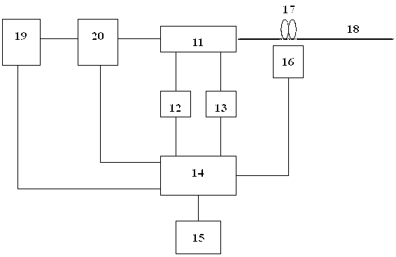
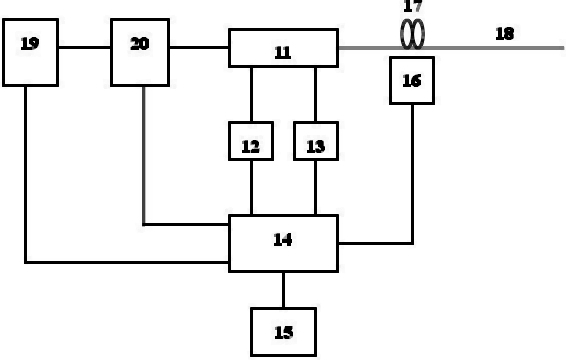
[0019] refer to figure 1, a distributed optical fiber Raman temperature sensor pulsed fiber laser 19 using cyclic pulse code decoding and Rayleigh demodulation, an acousto-optic modulator 20, an integrated optical fiber wavelength division multiplexer 11 with four ports, two photoelectric receiving amplifiers Modules 12 and 13, codec and demodulation digital signal processor 14, optical fiber temperature sampling loop 17, intrinsic temperature measuring optical fiber 18, digital temperature detector 16 and PC 15, output end of pulsed fiber laser 19 and acousto-optic An input end of the modulator 20 is connected, the output end of the acousto-optic modulator 20 is connected with the input port of the integrated optical fiber wavelength division multiplexer 11, and the first output port of the integrated optical fiber wavelength division multiplexer 11 is connected with the fiber te...


PUM

PropertyMeasurementUnit
wavelengthaaaaaaaaaa

Abstract

The invention discloses a distribution-type optical-fiber Raman temperature sensor adopting circulating pulse coding and decoding and Rayleigh demodulation, and the sensor comprises a pulse optical-fiber laser, an acoustic-optic demodulator, an integrated optical-fiber wavelength division multiplexer with four ports, two photoelectric receiving amplification modules, a coding-decoding demodulation digital signal processor, an optical-fiber temperature sampling ring, an intrinsic temperature measuring optical fiber, a digital temperature detector and a personal computer (PC). The sensor codes and decodes a signal on the basis of the circulating S matrix conversion, and the online location temperature measurement of the optical fiber is realized by utilizing an effect that the optical-fiber Raman optical strength is demodulated by the temperature and utilizing an optical time domain reflection principle. The circulating laser pulse coding and decoding is realized, and a Rayleigh channel is used as a temperature demodulation reference channel, so that the signal-to-noise ratio of the system is greatly improved, and the measuring precision and the measuring distance of the system are improved.

Description

technical field [0001] The invention relates to a distributed optical fiber Raman temperature sensor, in particular to a distributed optical fiber Raman temperature sensor adopting cyclic pulse code decoding and Rayleigh demodulation, and belongs to the technical field of optical fiber sensing. Background technique [0002] Distributed optical fiber temperature sensor system is a sensor system for real-time measurement of spatial temperature field distribution. In the system, optical fiber is both a transmission medium and a sensing medium. The distributed optical fiber Raman temperature sensor uses the Raman spectrum effect of the optical fiber. The temperature field of each point in the space where the optical fiber is located modulates the optical carrier transmitted in the optical fiber. After demodulation, the information of the spatial temperature field is displayed in real time. It is a special optical fiber communication system; using optical time domain reflection (...

Claims


Application Information

Patent Timeline
Patent Type & Authority Applications(China)
IPC IPC(8): G01K11/32G01K11/324
Inventor 余向东金尚忠张在宣李德和王剑锋张文生刘红林
Owner CHINA JILIANG UNIV
Why Eureka
Try Eureka