Diesel engine post-treatment system

A diesel engine and post-processing technology, which is applied in the direction of mechanical equipment, petroleum industry, engine components, etc., can solve the problems of reducing the effective flow area of ​​filters, high calibration development costs and hardware costs, and carrier cracking, so as to reduce carrier performance and Consistency requirements, reduced oxidation capacity and high temperature stability requirements, maximum temperature and the effect of temperature gradient reduction

Inactive Publication Date: 2012-10-17
杨德胜
View PDF0 Cites 5 Cited by
  • Summary
  • Abstract
  • Description
  • Claims
  • Application Information

AI Technical Summary

Problems solved by technology

[0005] These two regeneration technologies have been applied in developed countries such as Europe and the United States, but they have encountered certain application difficulties in China.
For the solution of using noble metal catalysts, firstly, because the sulfur content in diesel oil in most parts of the country is generally around 1000PPM, or even higher, it is easy to cause poisoning and failure of noble metal catalysts (negating the application of this technical solution); secondly, there are a large number of existing domestic Diesel engines in China do not use electronic control technology and fuel systems with multiple fuel injection functions (common rail fuel system, etc.), so the way to achieve regeneration through in-cylinder secondary injection technology cannot be realized on a large number of socially owned vehicles; finally, Since the exhaust gas temperature must be heated to above 550°C during the active regeneration process, local high temperature areas and large temperature gradients are likely to occur in the carrier during the regeneration process, so the carrier is prone to melting or cracking under variable active regeneration conditions Therefore, there are high requirements for the engine control system and carrier quality; but unfortunately, our countr

Method used


Image

  • Diesel engine post-treatment system

Examples


Embodiment Construction

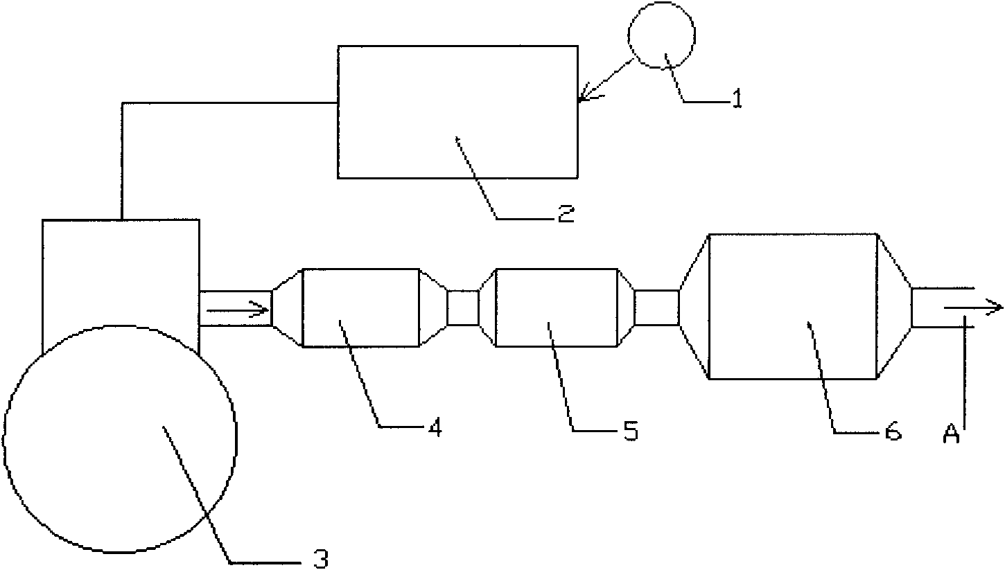
[0017] The present invention will be described in detail below with reference to the accompanying drawings, which is a preferred embodiment among various implementations of the present invention.

[0018] The first is to regularly add fuel additives with Fe or Ce as the main component to the fuel tank manually or automatically, and then enter the cylinder together with the fuel through the fuel injection system. The fuel additive basically does not participate in the combustion, and is discharged out of the cylinder together with the exhaust gas during the exhaust process, and adheres to the soot particles in the exhaust gas. When the exhaust gas flows through the partial flow-through metal filter, 30%-70% of the soot particles are captured, and more than 90% of the remaining soot in the exhaust gas will be captured by the downstream wall-flow ceramics. The above process is a typical soot particle capture process.

[0019] When the engine exhaust temperature exceeds 250°C, th...


PUM


Abstract

The invention relates to a diesel engine post-treatment system, comprising a tight coupling oxidation catalytic reactor, a first-grade flow-through type metal filter and a wall-flow type ceramic filter, wherein the tight coupling oxidation catalytic reactor is arranged on an outlet of an exhaust manifold (a natural aspirated diesel engine) or an turbine outlet of an exhaust gas turbocharger (a turbocharged diesel engine), the part flow-through type metal filter is arranged behind the tight coupling oxidation catalytic reactor, and a wall-flow type ceramic filter is arranged behind the first-grade flow-through type metal filter. In addition, a fuel oil additive including Fe or Ce is injected into a fuel tank and mixed with fuel oil, and then the obtained product is injected into a cylinder. The system can reduce the regeneration temperature of soot caught by a filtration system to 400 DEG C so as to reduce the energy needed to be consumed in a regeneration process, and in addition, risks of scorification or cracking of the ceramic filter in the regeneration process can be largely reduced. Finally, ash content collected into the metal filter can be cleaned by high pressure air back flushing or other ways after the filter is removed.

Description

technical field [0001] The invention relates to a diesel engine exhaust aftertreatment technology, in particular to a diesel engine aftertreatment system. Background technique [0002] For diesel engines, the main exhaust pollutants are particulate matter (Particulate Matter), and most of them are soot particles, so diesel engines with poor emissions always see a lot of black smoke. As the emission regulations of various countries in the world continue to become stricter, DPF (Diesel Particulate Filter) has been widely used in Europe, America and other countries. [0003] The commonly used DPF uses a wall-flow ceramic filter, which can trap 90% of the soot in the exhaust due to its special carrier structure. In addition, there are a variety of partial flow filters with different structures, mainly made of metal materials. This type of filter can only capture 30%-70% of the soot in the exhaust soot. In addition, when soot particles are trapped in the filter carrier, the flo...

Claims


Application Information

Patent Timeline
IPC IPC(8): F01N3/035C10L1/12F01N3/025F01N3/027
Inventor 杨德胜
Owner 杨德胜
Why Eureka
Try Eureka