Metal microparticle composite
A technology for metal particles and composites, applied in the measurement of color/spectral properties, nanotechnology, instruments, etc., can solve the problems of uneven distribution of metal particles, difficulty in miniaturization of measuring devices, unstable intensity or sharpness of absorption spectrum, etc. , to achieve the effect of simple composition
- Summary
- Abstract
- Description
- Claims
- Application Information
AI Technical Summary
Problems solved by technology
Method used
Image
Examples
no. 1 Embodiment approach
[0066] First, the metal microparticle composite and its manufacturing method according to the first embodiment of the present invention will be described.
[0067]
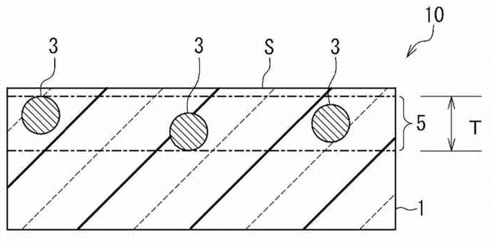
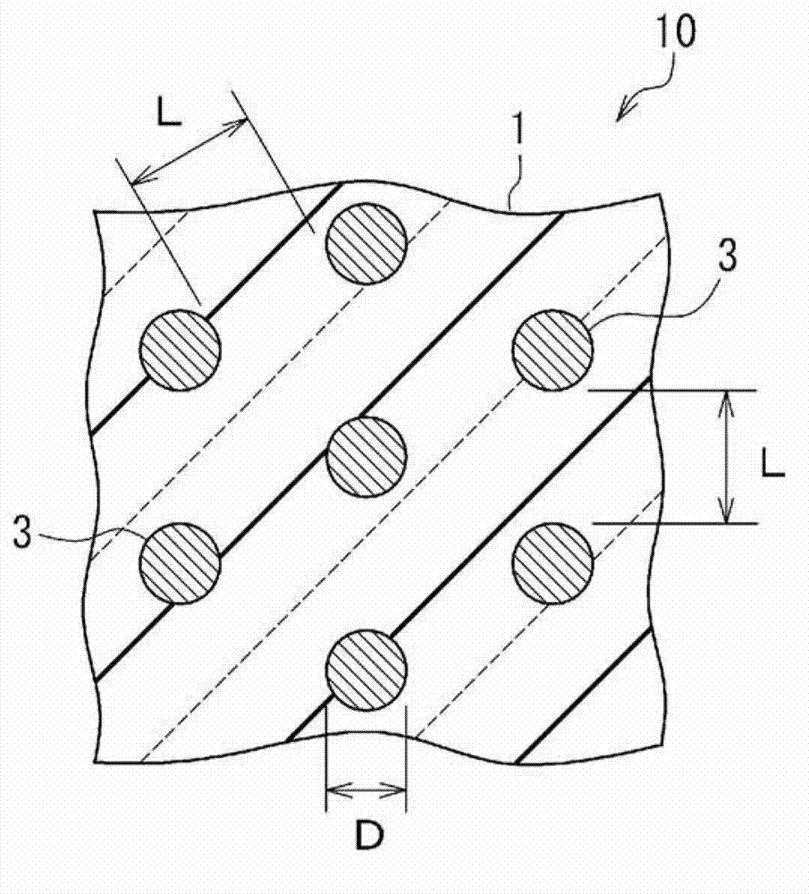
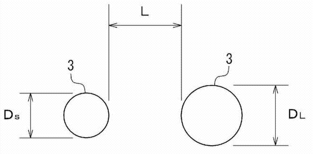
[0068] figure 1 A cross-sectional structure in the thickness direction of a metal microparticle-dispersed nanocomposite (hereinafter also simply referred to as "nanocomposite") 10 as the metal microparticle composite of the present embodiment is schematically shown. The nanocomposite 10 includes a matrix resin 1 and metal fine particles 3 immobilized in the matrix resin 1 . figure 2 Schematically shows the cross-sectional structure of the nanocomposite 10 in the plane direction, image 3 It is an enlarged view illustrating the metal microparticles 3 .
[0069] The nanocomposite 10 may also include an unillustrated base material. As such substrates, for example, glass, ceramics, silicon wafers, semiconductors, paper, metals, metal alloys, metal oxides, synthetic resins, organic / inorganic composite materials, ...
no. 2 Embodiment approach
[0172] Next, a second embodiment of the present invention will be described in detail.
[0173]
[0174] Figure 5 The cross-sectional structure in the thickness direction of the metal microparticle-dispersed nanocomposite 20 as the metal microparticle composite of the present embodiment is schematically shown. The nanocomposite 20 includes a matrix resin 1 , metal microparticles 3 immobilized in the matrix resin 1 , and bonding species 7 immobilized on a part or all of the metal microparticles 3 . Figure 6 It is an enlarged view illustrating the metal microparticles 3 (however, in a state where the chemical species 7 is not immobilized). in addition, Figure 6 The particle size of the larger metal particle 3 among the adjacent metal particles 3 is represented as D L , express the particle size of the smaller metal particle 3 as D S , when the two are not distinguished, it is only expressed as the particle size D.
[0175] In addition, the nanocomposite 20 may include ...
Synthetic example 1
[0283] In a 500 ml separable flask, 15.24 g of 2,2'-bis(trifluoromethyl)-4,4'-diaminobiphenyl (TFMB) 47.6 mmol was dissolved in 170 g of DMAc while stirring. Next, 14.76 g of 4,4'-oxydiphthalic anhydride (ODPA) 47.6 mmol was added to the solution under nitrogen flow, and the polymerization reaction was carried out at room temperature for 4 hours with continuous stirring to obtain a colorless viscous polymer. Amic acid resin solution S 1 . The resulting polyamic acid solution S 1 The viscosity was 3251 cP (25° C.) as a result of measurement with an E-type viscometer (manufactured by Brookfield, DV-II+Pro CP type). The weight average molecular weight (Mw) was measured by gel permeation chromatography (GPC; Tosoh Corporation make, HLC-8220GPC), and it was Mw=163900.
[0284] The resulting polyamic acid resin solution S 1 Coated on a stainless steel substrate, dried at 125°C for 3 minutes, then 2 minutes at 160°C, 30 minutes at 190°C, 30 minutes at 200°C, 3 minutes at 220°C, 2...
PUM
| Property | Measurement | Unit |
|---|---|---|
| particle diameter | aaaaa | aaaaa |
| thickness | aaaaa | aaaaa |
| particle diameter | aaaaa | aaaaa |
Abstract
Description
Claims
Application Information
 - R&D
- Intellectual Property
- Life Sciences
- Materials
- Tech Scout
- Unparalleled Data Quality
- Higher Quality Content
- 60% Fewer Hallucinations
Browse by: Latest US Patents, China's latest patents, Technical Efficacy Thesaurus, Application Domain, Technology Topic, Popular Technical Reports.
© 2025 PatSnap. All rights reserved.Legal|Privacy policy|Modern Slavery Act Transparency Statement|Sitemap|About US| Contact US: help@patsnap.com


