
Device and method for performing pyrolysis on solid fuel and performing reductive coupling on iron ore

A solid fuel, iron ore technology, applied in the field of iron ore reduction and fuel chemical industry, can solve problems such as restrictions and environmental pollution, and achieve the effects of enhancing the degree of contact, reducing costs, and reducing dust content

Active Publication Date: 2013-01-23
INST OF PROCESS ENG CHINESE ACAD OF SCI
View PDF4 Cites 8 Cited by
  • Summary
  • Abstract
  • Description
  • Claims
  • Application Information

AI Technical Summary

Problems solved by technology

The traditional blast furnace ironmaking is facing severe challenges due to the limitation of coking coal resources and the environmental pollution caused by the coking industry.

Method used


Image

  • Device and method for performing pyrolysis on solid fuel and performing reductive coupling on iron ore

Examples


Embodiment 1

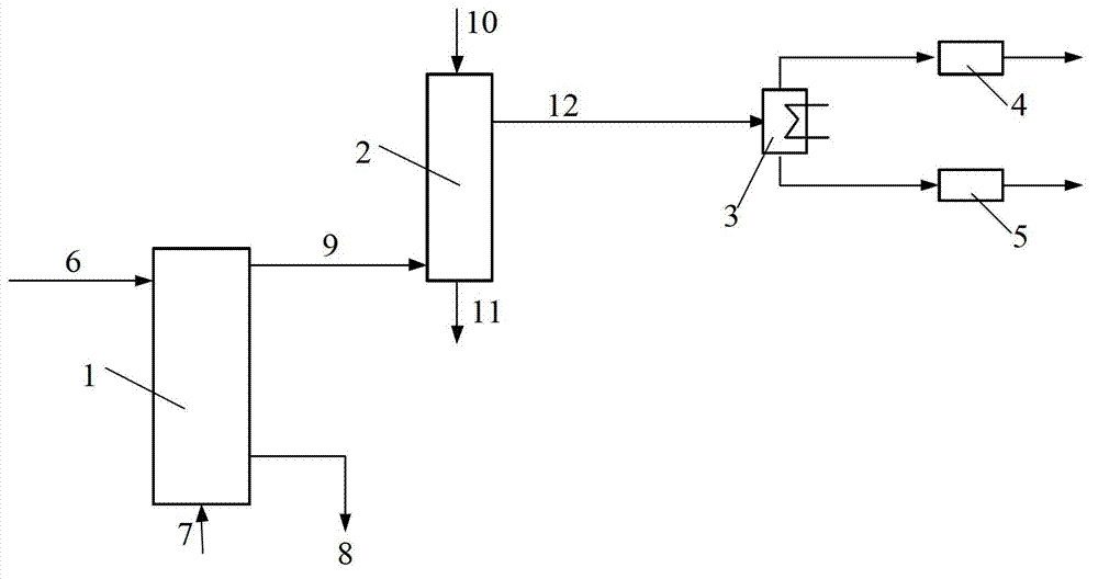
[0045] The lignite raw material is fed into the fluidized bed pyrolysis reactor from the solid fuel feed pipe, and under the action of the carrier gas nitrogen introduced from the carrier gas inlet pipe, pyrolysis occurs at a pressure of 0.1Mpa and a temperature of 650°C. Pyrolysis oil, pyrolysis gas and pyrolysis semi-coke are obtained, and the pyrolysis semi-coke is discharged from the pyrolysis semi-coke discharge pipe to obtain semi-coke products; the discharged pyrolysis oil and pyrolysis gas are discharged from the countercurrent moving bed reactor The lower part enters and contacts with the iron ore fed by the iron ore feeding pipe in countercurrent, and the heavy components in the pyrolysis oil continue to be cracked under the action of iron ore at 950°C to generate light tar, while the iron ore The rock is reduced to elemental iron and discharged from the elemental iron discharge pipe at the bottom of the reactor; the light tar and pyrolysis gas produced by cracking ar...

Embodiment 2

[0047] In this embodiment, the same experimental method as in Example 1 is adopted, the difference is that the pyrolysis reactor adopts a fixed bed reactor; the pressure is 6MPa, and the carrier gas is a hydrogen-rich reducing gas; the temperature at which the pyrolysis reaction occurs in the fixed bed reactor The temperature of the countercurrent moving bed reactor is 800°C.

Embodiment 3

[0049] In this embodiment, the same experimental method as in Example 1 is adopted, the difference is that the pyrolysis reactor is a moving bed reactor; the solid fuel is Jilin Huadian oil shale; the carrier gas is hydrogen; the pyrolysis reaction occurs in the moving bed reactor The temperature is 500°C and the pressure is 1MPa; the temperature of the countercurrent moving bed reactor is 750°C.


PUM

PropertyMeasurementUnit
boiling pointaaaaaaaaaa

Abstract

The invention relates to a device for performing pyrolysis on solid fuel and performing reductive coupling on iron ore. The device comprises a pyrolysis reactor, a counterflow moving bed reactor, a condensation separator, a gas purifier and a liquid purifier. A method for performing pyrolysis on the solid fuel and performing reductive coupling on the iron ore comprises the following steps of: performing pyrolysis on the solid fuel in the pyrolysis reactor under the action of inert gas or hydrogen-enriched reductive gas to obtain pyrolytic tar, pyrolysis gas and a semicoke product; feeding the pyrolytic tar and the pyrolysis gas into the counterflow moving bed reactor and performing countercurrent contact on the pyrolytic tar, the pyrolysis gas and the iron ore in the reactor to ensure that heavy components in the pyrolytic tar are subjected to pyrolysis continuously under the action of the iron ore to obtain light tar, and reducing the iron ore to obtain elementary substance iron; and condensing the generated pyrolysis gas and the light tar, separating and purifying to obtain the pyrolysis gas and the light tar product. The method has the characteristics that the light tar is obtained by performing pyrolysis on the heavy components in the tar by using the natural iron ore, so that the quality of the tar is improved; and meanwhile, the iron ore is reduced to form the elementary substance iron, so that the grade of ore is improved.

Description

technical field [0001] The invention relates to the fields of fuel chemical industry and iron ore reduction, in particular to a device and method for coupling solid fuel pyrolysis and iron ore reduction. Background technique [0002] Solid fuels belong to a large category of fuels, specifically solid combustible substances that can generate heat or power, and most of them contain carbon or hydrocarbons. Natural ones include wood, coal, oil shale, etc. Among them, coal is not only energy, but also an important source of valuable C and H resources and a variety of high-value chemicals, and my country is a country rich in coal, less in gas, and poor in oil. Coal is an important pillar of my country's economic development, so the development of clean and comprehensive utilization methods of coal is an inevitable requirement of my country's energy structure and industrial development. [0003] At present, the direct combustion of coal is still the main way of utilization in my co...

Claims


Application Information

Patent Timeline
Patent Type & Authority Applications(China)
IPC IPC(8): C10B49/02C10B57/00C10G55/04C10J3/20C10J3/02C10J3/82C21B13/00
Inventor 李松庚宋文立郝丽芳林伟刚
Owner INST OF PROCESS ENG CHINESE ACAD OF SCI
Learn More