
Composite thermally-conductive thin layer and preparation method and application thereof

A thin-layer, heat-conducting medium technology, applied in the field of preparation of functional composite materials, can solve the problems of poor thermal conductivity, decreased impact and delamination performance, and difficult dispersion of carbon nanotubes.

Active Publication Date: 2013-02-06
AVIC BEIJING INST OF AERONAUTICAL MATERIALS
View PDF9 Cites 40 Cited by
  • Summary
  • Abstract
  • Description
  • Claims
  • Application Information

AI Technical Summary

Problems solved by technology

However, there are few reports on the improvement of thermal conductivity of continuous carbon fiber composite materials. Related reports include: 46th InternationalSAMPE Symposium and Exhibition.2001: Materials and Processes Odyssey (2): 1530-1537, adding boron nitride directly between layers fine powder, but it will inevitably lead to the decline of impact delamination performance; Carbon, 50 (3): 1135-1145, 2011 added graphite nanosheet paper between the layers, but the author did not point out the graphite nanosheet paper inserted between the paper layers Contributes to the interlayer toughness of composite materials; Carbon, 49 (8): 2817-2833, 2010 incorporates carbon nanotubes, but the dispersion of individual carbon nanotubes is a difficult point, and it is difficult for laminated resin-based composites In particular, there are different opinions on the toughening effect of aviation-grade resin-based composites
Although this technique of introducing a tough structure between layers improves the toughness of the composite material, it also increases the gap between the carbon fiber resin-rich layers to a certain extent, and this tough structure usually has a thermal conductivity similar to that of the interlayer resin. rate, thus making the layer with high thermal resistance become less thermally conductive

Method used


Image

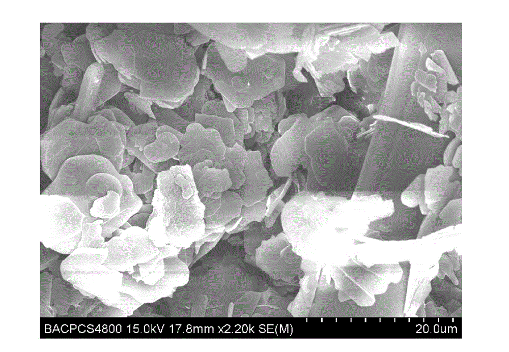
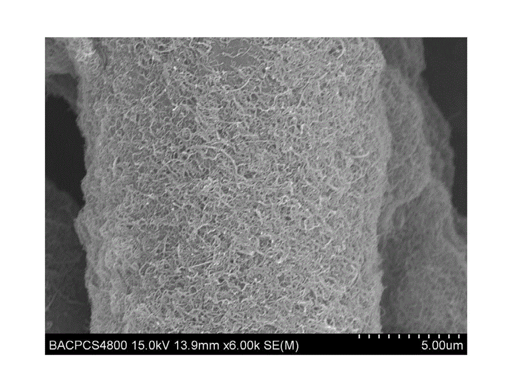
  • Composite thermally-conductive thin layer and preparation method and application thereof
  • Composite thermally-conductive thin layer and preparation method and application thereof

Examples


Embodiment 1

[0026] The implementation process of the technical solution of the present invention is as follows:

[0027] (1-1) Disperse carbon nanotubes or graphene in ethanol or isopropanol or acetone or ethylene glycol to form a dispersion with a concentration of 5 mg / mL or 15 mg / mL;

[0028] (1-2) Nylon non-woven fabric with a thickness of 53 μm and an area density of 14 g / m2 or a thickness of 25 μm and an area density of 8 g / m 2 Polyether ether ketone non-woven fabric or thickness of 75μm, surface density of 26g / m 2 Polyimide non-woven fabric with a thickness of 15μm and a surface density of 7g / m 2 Polyethersulfone non-woven fabric or thickness of 55μm, area density of 28g / m 2 Immerse the aramid non-woven fabric obtained in the above step (1-1) into the dispersion liquid obtained in the above step (1-1), pull it out of the liquid surface and dry it or dry it, turn it over and then dip it twice to obtain a uniformly loaded carbon nanotube or graphene Thermally conductive polymer non...

Embodiment 2

[0033] The implementation process of the technical solution of the present invention is as follows:

[0034] (2-1) Disperse flaky boron nitride powder or diamond micropowder or flake graphite powder in methanol or ethanol to form a 25 mg / mL or 40 mg / mL or 95 mg / mL dispersion.

[0035] (2-2) Use the method of filtering the dispersion liquid in step (2-1) to be loaded to a thickness of 35 μm and a surface density of 14 g / m 2 Nylon fabric with a thickness of 25μm and a surface density of 11g / m 2 Polyether ether ketone fabric or thickness of 45μm, area density of 18g / m 2 On the polyimide fabric, obtain the heat conduction thin layer fabric that heat conduction medium attaches;

[0036](2-3) Lay the thermally conductive polymer porous films obtained above on one by one between the layers of continuous carbon fiber reinforced satin or plain weave or unidirectional or a mixture of the above weaving methods, carbon fiber T700, 12K, After shaping, a prefabricated composite material ...

Embodiment 3

[0039] The implementation process of the technical solution of the present invention is as follows:

[0040] (3-1) Co-disperse graphene, carbon nanotubes or carbon nanotubes, flake boron nitride powder in butanol or methanol or tetrahydrofuran to form a dispersion, the concentrations are: graphene concentration 6mg / mL, carbon nanometer Tube concentration is 9mg / mL, or carbon nanotube concentration is 8mg / mL, flake boron nitride powder concentration is 20mg / mL.

[0041] (3-2) Spray the above-mentioned co-dispersion of heat-conducting medium to a thickness of 75 μm and an area density of 26 g / m 2 The polyimide fiber non-woven fabric or the thickness is 28μm, the area density is 11g / m 2 Carbon nanofiber non-woven fabric with a thickness of 5μm and a surface density of 5g / m 2 On the carbon nanotube non-woven fabric, a composite heat-conducting thin layer of graphene, carbon nanotubes or carbon nanotubes and flake boron nitride powder is obtained;

[0042] (3-3) Place the heat-c...


PUM

PropertyMeasurementUnit
Thicknessaaaaaaaaaa
Areal densityaaaaaaaaaa
Thicknessaaaaaaaaaa

Abstract

The invention relates to design and a preparation technique of continuous laminated carbon fiber reinforced resin matrix composite high in thermal conductivity and toughness, and intermediate composite thermally-conductive thin layers and finished composite products of the continuous laminated carbon fiber reinforced resin matrix composite. The preparation technique is mainly characterized in that meshed low-surface-density nonwoven, a porous membrane or fabric are used as functional carriers to carry one or mixture of some of high-thermal-conductivity, nano-micron and small-scale carbon nanotubes, graphene, boron nitride micropowder, expanded graphene micropowder, diamond micropowder and the like so as to prepare the composite thermally-conductive thin layer with high thermal conductivity and toughening potential, the composite thermally-conductive thin layer is placed between layers of conventional carbon fiber laminated composite by intercalation technology, and forming and curing are performed to prepare the structural composite high in overall thermal conductivity and toughness. The preparation technique is simple to operate. The toughness of the obtained composite is improved greatly, inter-layer and intra-layer thermal conductivities are both improved, and the obtained composite is high in overall thermal conductivity and toughness.

Description

technical field [0001] The present invention relates to a composite heat-conducting thin layer and its preparation method and application. The technology includes the preparation technology of a heat-conducting thin layer with high thermal conductivity and toughening effect and the overall high thermal-conducting and high-toughness structure prepared by using the heat-conducting thin layer. A composite material belongs to the technical field of preparation of functional composite materials. Background technique [0002] Continuous carbon fiber reinforced resin-based laminated composites have high specific strength and specific stiffness, and are increasingly used as structural materials in aerospace and civil fields. However, due to the structural characteristics of this composite material, although carbon fiber itself is in The fiber direction has a high thermal conductivity, but the resin-rich region between the layers has a very low thermal conductivity similar to most or...

Claims


Application Information

Patent Timeline
IPC IPC(8): B32B9/04B32B3/24B32B27/02B32B27/06B32B37/02B32B27/04
Inventor 益小苏郭妙才刘刚赵文明
Owner AVIC BEIJING INST OF AERONAUTICAL MATERIALS
Learn More