Coal thermolysis device for heat-carrying gas

A technology of coal pyrolysis and heat transfer, which is applied in the direction of gas fuel, charging device, unloading device, etc., can solve the problems of easy clogging of casing materials, lower thermal efficiency than direct utilization, uneven heating of middle casing, etc. Achieve the effects of shortening coking time, low cost and low equipment wear rate

Inactive Publication Date: 2013-02-06
TAIYUAN UNIV OF TECH
View PDF11 Cites 15 Cited by
  • Summary
  • Abstract
  • Description
  • Claims
  • Application Information

AI Technical Summary

Problems solved by technology

The disadvantage of this device is that the sensible heat recovery device uses the heat recovered by the steam generator to generate medium-high pressure steam, which is then used for heat exchange in the process, and indirectly utilizes the sensible heat of high-temperature synthesis gas. The thermal efficiency is lower than that of direct utilization. Increased investment in equipment
The disadvantages of this device are: the arrangement of air and gas nozzles on the furnace wall of the heat transfer chamber is likely to cause gas leakage and carbon deposition, and the furnace wall in the heat transfer chamber facing away from the retort chamber has a large heat dissipation, resulting in high heat loss
The shortcomings of this device are: (1) The thin-layer annular space structure of the middle casing and the multi-layer inverted tapered baffles inside it result in a small single furnace production capacity, which does not utilize the needs of industrial production, and the casing inside the casing The material is prone to blockage, which affects the heat transfer and the control of the material in and out; (2) The unreasonable structure of the outer casing and the inner casing will directly lead to uneven heating on both sides of the middle casing, and the flue gas used to heat the middle casing, Without adding any stirring device to increase its heat transfer, it is directly discharged into the atmosphere through the outer casing and the inner casing after exchanging heat. This structural setting results in a higher flue gas outlet temperature and increases heat loss.

Method used


Image

  • Coal thermolysis device for heat-carrying gas
  • Coal thermolysis device for heat-carrying gas
  • Coal thermolysis device for heat-carrying gas

Examples


Embodiment Construction

[0024] Specific embodiments of the present invention will be described below in conjunction with the accompanying drawings.

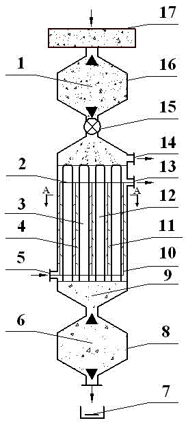
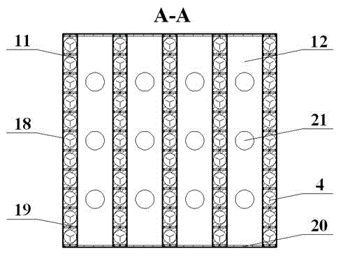
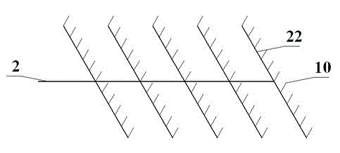
[0025] as attached figure 1 , attached figure 2 And attached image 3 As described above, a heat-carrying gas provided by the present invention is used in a pyrolysis device for coal. From top to bottom, the pyrolysis device is composed of a feeding and gas collection section 1 , a dry distillation section 3 and a semi-coke collection section 6 .

[0026] The feeding system of the upper feeding and gas collection section 1 adopts the structure of coal lock 16 and screw feeder 15, and the coal material coming out of coal hopper 17 is completed by screw feeder 15 from coal lock 16 to carbonization chamber 12, wherein the coal Lock 16 and screw feeder 15 control the feeding amount of coal material. The lower part of the feeding and gas collection section 1 is provided with a raw gas export pipeline and a raw gas outlet 14, so that the raw gas generate...


PUM


Abstract

The invention provides a coal thermolysis device for heat-carrying gas. The coal thermolysis device is formed by correspondingly fastening two metal plates in which a plurality of semicircular concave grooves are arranged according to the concave grooves, wherein the plurality of semicircular concave grooves are combined to form a plurality of heat-carrying gas heat transmission pipes; the heat transmission pipes are sequentially communicated with a small vertical pipe, a transverse pipe, a main pipe, a heat-carrying gas inlet and a heat-carrying gas outlet, so as to form a heat-carrying gas heat transmission system. According to the coal thermolysis device, the heat-carrying can be used for directly drying the coal in a destructive distillation chamber through a metal heat intromission pipe, so as to achieve normal-pressure or destructive distillation; and the coal thermolysis device has the characteristics of being fast in transmission rate, high in heat utilization rate, simple in structure and low in cost.

Description

technical field [0001] The invention relates to a coal pyrolysis device, specifically, a coal pyrolysis device with a heat-carrying gas structure constituting a heat-carrying gas heat transfer system. Background technique [0002] Pyrolysis or dry distillation of coal refers to the process in which coal is thermally decomposed under the condition of isolation of air, that is, under the condition of lack of oxygen, to produce raw gas, tar, coke (or semi-coke) and other products. Low-temperature dry distillation technology mostly uses low-rank coal such as non-caking coal, weakly caking coal, long-flame coal or lignite as raw materials for pyrolysis or dry distillation, and the reserves of low-rank coal in my country are relatively large, accounting for more than 42% of coal reserves , to provide rich raw materials for low temperature dry distillation technology. The pyrolysis or carbonization furnace is the main equipment in the low temperature carbonization production proces...

Claims


Application Information

Patent Timeline
Patent Type & Authority Applications(China)
IPC IPC(8): C10B15/00C10B47/00C10B57/10C10B57/02C10B57/00C10B31/00C10B33/00C10L3/08C10L3/10C07C9/04C07C1/02
Inventor 张永发陈磊武云霞唐健丁晓阔张天开孙亚玲
Owner TAIYUAN UNIV OF TECH
Why Eureka
Try Eureka