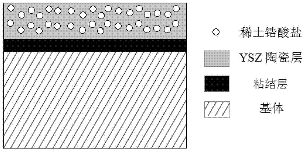
In-situ synthesis method for preparing composite thermal barrier coating
A thermal barrier coating, in-situ synthesis technology, applied in coatings, metal material coating processes, air transportation, etc., can solve the problem of reducing the thermal conductivity of materials, reducing the mean free path of phonons, and increasing the phonons of ceramic layers. Scattering and other problems, to extend service life, improve thermal stability and anti-oxidation performance, and achieve good matching results
- Summary
- Abstract
- Description
- Claims
- Application Information
AI Technical Summary
Problems solved by technology
Method used
Image
Examples
Embodiment 1
[0027] The bonding layer in the workpiece thermal barrier coating is NiCrAlY coating, in which the mass fractions of Ni, Cr, Al and Y are 69%, 20%, 10% and 1%, respectively, and the thickness is 100 μm. After surface treatment, La 2 Zr 2 o 7 The preparation method of the / YSZ composite ceramic layer is realized according to the following steps:
[0028] a the La with a molar ratio of 1:2 2 o 3 and ZrO 2 Powder mixing and ball milling for 48 hours;
[0029] b ball milled La 2 o 3 / ZrO 2 The mixed powder and YSZ powder are mixed at a molar ratio of 1:2;
[0030] c. Spray the mixed powder obtained in step b on the surface of the bonding layer by plasma spraying method, and the thickness of the ceramic coating is 300 μm. Spraying parameters: voltage 74V, current 650A, powder feeding rate 60g min -1 , argon flow rate 2550L h -1 , hydrogen flow rate 425L h -1 , the spraying distance is 120mm;
[0031] d Place the sprayed thermal barrier coating ceramic layer in a resis...
Embodiment 2
[0033] The bonding layer in the workpiece thermal barrier coating is NiCrAlY coating, in which the mass fractions of Ni, Cr, Al and Y are 69%, 20%, 10% and 1%, respectively, and the thickness is 80 μm. After surface treatment, Nd 2 Zr 2 o 7 / YSZ conforms to the preparation method of the ceramic layer according to the following steps:
[0034] a Add Nd with a molar ratio of 1:2 2 o 3 and ZrO 2 Powder mixing and ball milling for 72 hours;
[0035] b ball milled Nd 2 o 3 / ZrO 2 The mixed powder and YSZ powder are mixed at a molar ratio of 1:4;
[0036] c. Spray the mixed powder obtained in step b on the surface of the bonding layer by plasma spraying method, and the thickness of the ceramic coating is 200 μm. Spraying parameters: voltage 74V, current 650A, powder feeding rate 60g min-1 , argon flow rate 2550L h -1 , hydrogen flow rate 425L h -1 , the spraying distance is 100mm;
[0037] d Place the sprayed thermal barrier coating ceramic layer in a resistance furnace...
Embodiment 3
[0039] The bonding layer in the workpiece thermal barrier coating is NiCrAlY coating, in which the mass fractions of Ni, Cr, Al and Y are 69%, 20%, 10% and 1%, respectively, and the thickness is 120 μm. After surface treatment, Sm 2 Zr 2 o 7 The preparation method of the / YSZ composite ceramic layer is realized according to the following steps:
[0040] a Sm with a molar ratio of 1:2 2 o 3 and ZrO 2 Powder mixing and ball milling for 18 hours;
[0041] b Sm after ball milling 2 o 3 / ZrO 2 The mixed powder and YSZ powder are mixed in a molar ratio of 4:1;
[0042] c. Spray the mixed powder obtained in step b on the surface of the bonding layer by plasma spraying method, and the thickness of the ceramic coating is 400 μm. Spraying parameters: voltage 74V, current 650A, powder feeding rate 60g min -1 , argon flow rate 2550L h -1 , hydrogen flow rate 425L h -1 , the spraying distance is 150mm;
[0043] d Place the sprayed thermal barrier coating ceramic layer in a re...
PUM
| Property | Measurement | Unit |
|---|---|---|
| Thickness | aaaaa | aaaaa |
| Thickness | aaaaa | aaaaa |
| Thickness | aaaaa | aaaaa |
Abstract
Description
Claims
Application Information
 - R&D
- Intellectual Property
- Life Sciences
- Materials
- Tech Scout
- Unparalleled Data Quality
- Higher Quality Content
- 60% Fewer Hallucinations
Browse by: Latest US Patents, China's latest patents, Technical Efficacy Thesaurus, Application Domain, Technology Topic, Popular Technical Reports.
© 2025 PatSnap. All rights reserved.Legal|Privacy policy|Modern Slavery Act Transparency Statement|Sitemap|About US| Contact US: help@patsnap.com

