Method for in-situ growth of carbon nanotube array on metal current collector
A carbon nanotube array and in-situ growth technology, which is applied to structural parts, electrical components, battery electrodes, etc., can solve problems affecting electrical performance, etc., and achieve the effect of simple process, low equipment requirements, and good cycle stability
- Summary
- Abstract
- Description
- Claims
- Application Information
AI Technical Summary
Problems solved by technology
Method used
Image
Examples
Embodiment 1
[0040] Using ultra-high vacuum electron beam evaporation system at 5.0×10 -8 Under the pressure of mbar, aluminum oxide with a thickness of 30nm and iron with a thickness of 5nm are sequentially deposited on a tantalum foil with a thickness of 20μm and a purity of 99.95% at a rate of 0.05nm / s at room temperature to obtain an iron catalyst layer / alumina buffer layer / A substrate with a three-layer structure of metal tantalum foil; the substrate is placed in the central heating zone of a thermal CVD furnace, and the temperature is raised to 650°C at a rate of 10°C / min under the protection of argon, then the argon is closed, and hydrogen is introduced ( The hydrogen flow rate is 50sccm, the pressure is 0.5MPa) and pretreatment for 8 minutes; then acetylene, hydrogen and argon are introduced at the flow rates of 8sccm, 60sccm and 140sccm respectively, and the pressure in the furnace is raised to 5×10 under the above mixed atmosphere. 5 Pa, keeping the temperature for 1 hour and co...
Embodiment 2
[0047] Replace the "tantalum foil with a copper foil with a thickness of 20 μm and a purity of 99.95%" in Example 1, and prepare a carbon nanotube array and assemble a lithium-ion half-cell according to the process described in Example 1.
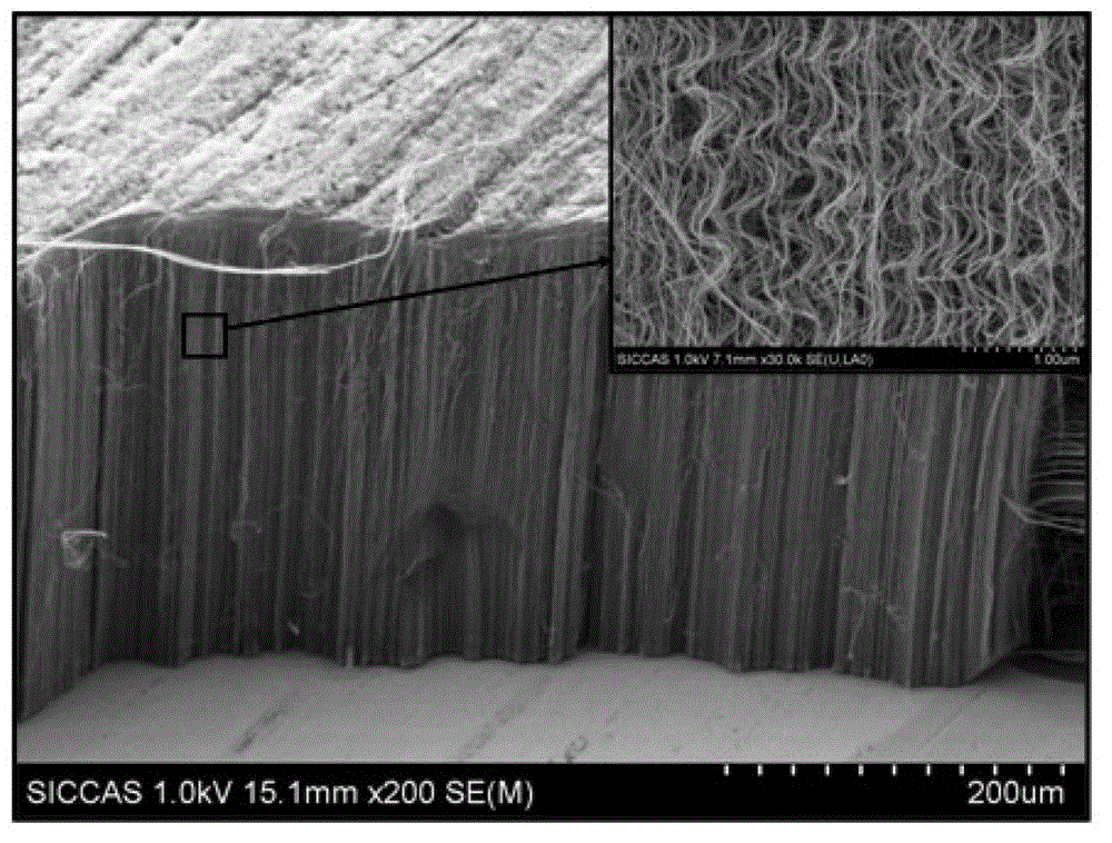
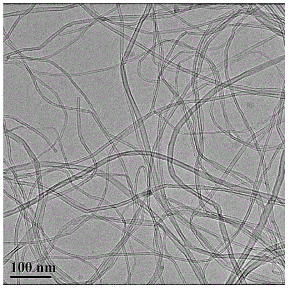
[0048] Figure 8 SEM photographs of the as-prepared carbon nanotube arrays, obtained by Figure 8 It can be seen that the prepared carbon nanotube array has a height of about 200 μm, a single carbon nanotube has a diameter of about 10 nm, has few walls, and each carbon nanotube is directly and firmly combined with the current collector.
[0049] In addition, it was found that the reversible specific capacity of the prepared carbon nanotube array negative electrode material was as high as 3437.8mAh / g after 46 charge-discharge cycles under the low-speed charge-discharge condition of 0.13C, and the specific capacity under the high-speed charge-discharge condition of 30C It is still as high as 265mAh / g, and after 2480 cycles, it still has a sp...
Embodiment 3
[0051] The carbon nanotube array was prepared and the lithium-ion half-cell was assembled according to the process described in Example 1, the only difference from Example 1 was that the thickness of the prepared iron catalyst layer was 1.2 nm.
[0052] After testing, it is known that the height of the prepared carbon nanotube array is about 300 μm, the diameter of a single carbon nanotube is about 6 nm, and the bonding strength with the metal substrate is slightly poor; The reversible specific capacity reaches 2980.7mAh / g after 46 charge-discharge cycles under low-speed charge-discharge conditions, and the specific capacity reaches 210mAh / g under high-speed charge-discharge conditions at 30C, and recharges and discharges at 0.13C after 2480 cycles It still has a specific capacity of 2788.8mAh / g when charging and discharging at a high rate, and has good cycle stability.
PUM
| Property | Measurement | Unit |
|---|---|---|
| Thickness | aaaaa | aaaaa |
| Thickness | aaaaa | aaaaa |
| Thickness | aaaaa | aaaaa |
Abstract
Description
Claims
Application Information
 - R&D
- Intellectual Property
- Life Sciences
- Materials
- Tech Scout
- Unparalleled Data Quality
- Higher Quality Content
- 60% Fewer Hallucinations
Browse by: Latest US Patents, China's latest patents, Technical Efficacy Thesaurus, Application Domain, Technology Topic, Popular Technical Reports.
© 2025 PatSnap. All rights reserved.Legal|Privacy policy|Modern Slavery Act Transparency Statement|Sitemap|About US| Contact US: help@patsnap.com


