
Perlite production equipment

A production equipment and perlite technology, which is applied in the building material production industry and the field of energy conservation and environmental protection, can solve the problems of serious environmental pollution, low output, and high energy consumption, and achieve the goals of improving the working environment, reducing energy consumption, and increasing equipment utilization. Effect

Inactive Publication Date: 2013-04-10
ZUNYI CITY GUI KE TECH
View PDF0 Cites 4 Cited by
  • Summary
  • Abstract
  • Description
  • Claims
  • Application Information

AI Technical Summary

Problems solved by technology

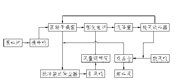
[0003] The purpose of the present invention is to provide a kind of perlite production equipment which is relatively energy-saving and does not pollute the environment in view of the problems of high energy consumption, serious environmental pollution and low output in the current domestic perlite production. It mainly consists of raw material pits, Elevator, rotary drying kiln, puffing furnace, dust collector, induced draft fan, air volume control valve, settling chamber, finished product warehouse, cyclone receiver, blower and joint ventilation pipe; the lower end of the elevator is in the raw material pit, and the upper end is connected to the rotary drying The discharge port of the rotary drying furnace is connected with the feed port of the puffing furnace, and the rotary drying furnace is connected with the dust collector through the pipe. It is connected to the settling chamber, and the settling chamber is connected to the cyclone receiver. One side of the cyclone receiver is connected to the finished product warehouse by the air duct, and the other side is connected to the blower. The cyclone receiver is also connected to the rotary drying kiln through the air duct. The whole system is in a closed-loop control state.

Method used


Image

  • Perlite production equipment
  • Perlite production equipment
  • Perlite production equipment

Examples


Embodiment Construction

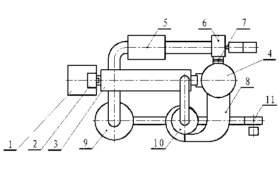
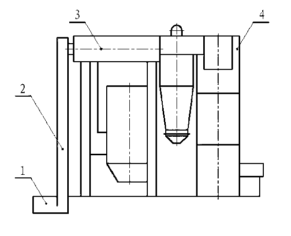
[0010] The present invention is described in detail below in conjunction with accompanying drawing: As shown in the figure, a kind of perlite production equipment mainly consists of raw material pit 1, elevator 2, rotary drying kiln 3, puffing furnace 4, dust collector 5, induced draft fan 6, air volume Regulating valve 7, settling chamber 8, finished product warehouse 9, cyclone receiver 10, blower 11 and joint ventilation pipe; the lower end of the elevator 2 is in the raw material pit 1, the upper end is connected with the rotary drying furnace 3, and the outlet of the rotary drying furnace 3 The feed port is connected to the feed port of the puffing furnace 4, and the rotary drying furnace 3 is also connected to the dust collector 5 by a pipe. 4 is connected to the settling chamber 8, and the settling chamber 8 is connected to the cyclone receiver 10. One side of the cyclone receiver 10 is connected to the finished product warehouse 9 by the air duct, and the other side is ...


PUM


Abstract

Perlite production equipment mainly comprises a raw material pit, an elevator, a rotary drying kiln, an expansion furnace, a dust remover, an induced draft fan, an air volume regulating valve, a settling chamber, a finished product bin, a cyclone material collector, an air blower and a communication air pipe. The lower end of the elevator is positioned in the raw material pit, the upper end of the elevator is connected with the rotary drying kiln, a discharge outlet of the rotary drying kiln is connected with a feed inlet of the expansion finance, the rotary drying kiln is communicated with the dust remover by a pipeline, the dust remover is connected with the induced draft fan by an air pipe and communicated with the expansion furnace via the air volume regulating valve, the expansion valve is communicated with the settling chamber, the settling chamber is communicated with the cyclone material collector, one side of the cyclone material collector is communicated with the finished product bin by an air pipe while the other side of the cyclone material collector is communicated with the air blower, the cyclone material collector is further communicated with the rotary drying kiln by an air pipe, and an integral system is in a closed-loop control state. The perlite production equipment is fast in temperature rise and easy in temperature control, ignition loss of a furnace body is little, the service life of the perlite production equipment is prolonged, expansion efficiency is improved, energy consumption is low, utilization rate is high, repair workload is low, automatic control is realized, labor is saved, an operating environment is enhanced, and emission of greenhouse gases is reduced.

Description

technical field [0001] The invention relates to the technical field of building material production industry and energy saving and environmental protection, in particular to an energy-saving and environment-friendly perlite production equipment. Background technique [0002] Perlite is an inorganic thermal insulation material, which has been widely used in metallurgy and building materials industries. The equipment for producing perlite has developed from coal-fired rotary drying kilns and coal-fired extruders to rotary drying with gas and electricity as heat sources. Kiln and puffing electric furnace. Grading recycling technology has been promoted and applied. However, the recovery and utilization of waste heat is still in the development stage, and a large amount of high-temperature flue gas is directly discharged into the atmosphere, causing energy waste and environmental pollution. Contents of the invention [0003] The purpose of the present invention is to provide ...

Claims


Application Information

Patent Timeline
IPC IPC(8): C04B14/18
Inventor 许善文李松刘远德袁志勇
Owner ZUNYI CITY GUI KE TECH
Learn More