
Giant magneto-impedance effect two-dimensional magnetic field sensor

A magnetic field sensor and giant magneto-impedance technology, applied in the field of sensors, can solve the problems of high production cost, unfavorable measurement signal, low finished product, etc., and achieve the effect of accurate size and precision, high magnetic field sensitivity, and guaranteed repeatability

Inactive Publication Date: 2013-04-10
周志敏 +2
View PDF1 Cites 22 Cited by
  • Summary
  • Abstract
  • Description
  • Claims
  • Application Information

AI Technical Summary

Problems solved by technology

Since the amorphous wire is generally prepared by wire drawing, its diameter is in the range of 10-50 microns, although its length can reach millimeters or even centimeters, it is not compatible with semiconductor processing technology, so the process of preparing the sensor can only be done manually. Or mechanically operated methods to achieve its positioning and processing
Secondly, in the process of preparing the signal induction coil, it is necessary to process a long groove with a depth of 50 microns on the substrate to accommodate and position the amorphous wire, and it is necessary to wrap the amorphous wire with silica gel or epoxy for insulation. Although the induction coil It can also be processed by semiconductor processes such as photolithography, but because semiconductor processes are generally realized based on planar processing, the production method has the characteristics of high production cost and low finished product, thereby increasing the production cost and the processed size. and position accuracy are low, which will adversely affect the measurement signal

Method used


Image

  • Giant magneto-impedance effect two-dimensional magnetic field sensor
  • Giant magneto-impedance effect two-dimensional magnetic field sensor

Examples


Embodiment Construction

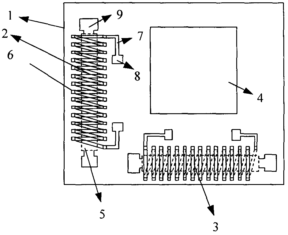
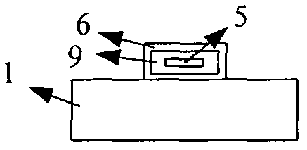
[0022] The specific structure of the present invention will be further described below in conjunction with the accompanying drawings.

[0023] Such as Figure 1-2 As shown, the present invention consists of two giant magnetoresistance magnetic sensors 2 and 3 on the substrate 1, and an integrated circuit signal processing module 4; the giant magnetoresistance two-dimensional magnetic field sensors 2 and 3 are made of soft magnetic amorphous thin Composed of belt 4, signal acquisition coil 5, insulating filling material 6, wire 7 and signal pin 8;

[0024] The soft magnetic amorphous thin strip 4 is placed on the axis position of the signal collection line pipe 5;

[0025] The anisotropy field of the soft magnetic amorphous ribbon is along the width direction of the ribbon;

[0026] The integrated circuit signal processing module 4 is used for the excitation signal of the soft magnetic amorphous strip 5 and the signal receiving and processing of the signal acquisition coil 5,...


PUM

PropertyMeasurementUnit
Frequencyaaaaaaaaaa
Pulse widthaaaaaaaaaa

Abstract

The invention relates to a giant magneto-impedance effect two-dimensional magnetic field sensor and belongs to the technical field of sensors. The sensor is composed of two orthogonal giant magneto-impedance effect magneto-dependent sensors 2 and 3 and an integrated circuit signal processing module 4. Each magneto-dependent sensor 2 or 3 is composed of an amorphous thin belt 4, a signal collection coil 5 with the thin belt as a magnetic core, an insulation filling material 6, a copper wire 7 at two ends and an electrode pin 8. An anisotropic filed of the thin belt of each sensor is in the width direction and is in linear or winding geometrical shape, and the sensors are manufactured by a micro electromechanical system (MEMS). When the sensors work, the signal processing module provides 0.1-100MHz high frequency alternating current signals or 0.1ns pulse signals flowing through the magnetic core, and the signal collection coil is used for sensing reaction of the magnetic core to an external magnetic field. Due to the fact that the magneto-dependent sensors have maximum sensitivity on magnetic fields in the line length direction, magnetic field components in a chip plane in the line length direction can be measured respectively to determine direction and size of the magnetic fields in the plane. The giant magneto-impedance effect two-dimensional magnetic field sensor can serve as an electronic compass to determine gesture of vehicles, mobile phones and the like, and has the advantages of being small in size, high in reaction sensitivity, high in response speed and low in power consumption.

Description

[0001] The invention relates to a magnetic field measuring device, in particular to a giant magneto-impedance effect two-dimensional magnetic field sensor, which belongs to the technical field of sensors. technical background [0002] The precise measurement of the space geomagnetic field is the basic principle of the electronic compass for determining the position and orientation of electronic equipment. Compared with the GPS global positioning system, it has the advantages of low price and convenient use, so it is widely used in various mobile devices such as mobile phones , cars, laptops, etc. Magnetic sensors constitute an important part of the electronic compass system. Common magnetic sensors include Hall Hall sensors. Although they can be processed by semiconductor technology and have a small size, they have weak output signal amplitude and low sensitivity. And it is easily affected by temperature. Magnetoresistive sensor, a new type of silicon-based magnetosensitive s...

Claims


Application Information

Patent Timeline
IPC IPC(8): G01R33/09B81C1/00
Inventor 周志敏
Owner 周志敏
Learn More