
Charge pump circuit used for charge pump phase-locked loop

A technology of charge pump and phase-locked loop, which is applied in the field of electronics, can solve the problems of current mirror current mismatch, influence of lower-level circuits, and failure to realize constant charging and discharging current, etc., and achieves the effects of easy integration, high matching accuracy, and simple structure

Inactive Publication Date: 2013-04-10
UNIV OF ELECTRONIC SCI & TECH OF CHINA
View PDF4 Cites 18 Cited by
  • Summary
  • Abstract
  • Description
  • Claims
  • Application Information

AI Technical Summary

Problems solved by technology

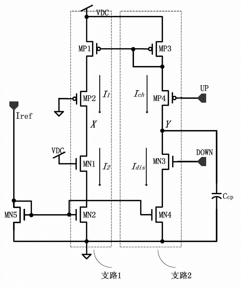
[0005] The disadvantages of this circuit are: 1. The current mismatch problem of the current mirror: due to the channel modulation effect, the V of the MP3 tube in the PMOS current mirror and the MN4 tube in the NMOS current mirror ds not equal, for example V cp ( figure 2 When the potential of point Y shown in ) is high, the drain voltage of MP4 and MN3 is high, then I ch dis , then during the reset pulse, MP4 and MN3 will be turned on, and the capacitor C cp will release the charge, V cp It will decrease and will not remain unchanged, which will affect the lower circuit
2. The problem of charge sharing: the MP3 tube in the PMOS current mirror and the MN4 tube in the NMOS current mirror are respectively close to the power supply and ground, and there is a certain capacitance in the drain. Assuming that the switch tubes MP4 and MP3 are disconnected, then the MP3 tube will charge the node Y to VDC, MN4 tube discharges node X to zero potential
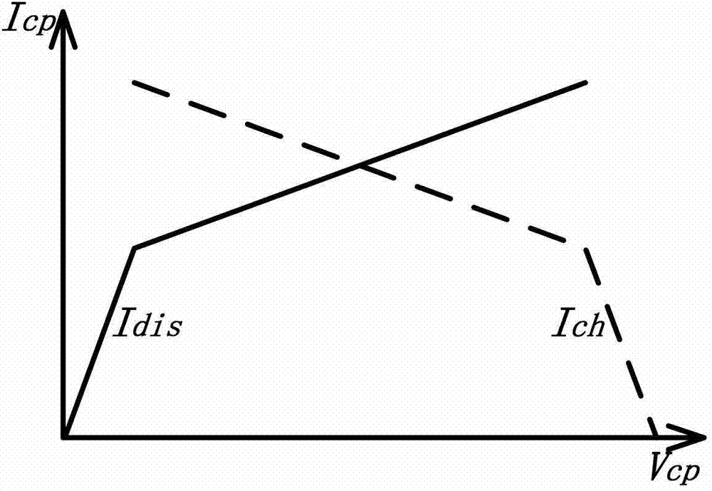
This circuit can be regarded as an improvement of the first charge pump circuit. First: a transconductance operational amplifier is added, and the potentials of X and Y points are equalized through feedback, thereby realizing equal charging and discharging currents; second: exchanging The position of the switch tube and the current mirror, which solves the problem of charge sharing, but from Figure 5 It can be seen from the waveform diagram that although the charge pump circuit Ich=Idis, but I ch , I dis It will change with the change of the output voltage, so it does not realize the constant charging and discharging current

Method used


Image

  • Charge pump circuit used for charge pump phase-locked loop
  • Charge pump circuit used for charge pump phase-locked loop
  • Charge pump circuit used for charge pump phase-locked loop

Examples


Embodiment Construction

[0019] The present invention will be further described below in conjunction with the accompanying drawings and specific embodiments.

[0020] A charge pump circuit for a charge pump phase-locked loop, such as Figure 6 As shown, it includes a charging and discharging unit, a first complementary circuit unit, a first operational amplifier unit A1, an inverter unit, a second complementary circuit unit, a current mirror unit and a second operational amplifier unit A2. The output terminal of the charging and discharging unit is connected to the negative input terminal of the first operational amplifier unit A1, the output terminal of the first complementary circuit unit is connected to the positive input terminal of the first operational amplifier unit A1, and the The output end of the first op-amp unit A1 is respectively connected to the first input end of the charging and discharging unit and the first input end of the first complementary circuit unit, and the input end of the i...


PUM


Abstract

The invention provides a charge pump circuit used for a charge pump phase-locked loop, and belongs to the technical field of electronics. The charge pump circuit comprises a charge and discharge unit, a first complementary circuit unit, a first operational amplifier unit, a phase inverter unit, a second complementary circuit unit, a current mirror unit and a second operational amplifier unit. According to the charge pump circuit, the problems of charge and discharge current matching and charge sharing of an existing charge pump circuit are resolved, the two complementary circuit units and the two operational amplifier units are used, the two complementary circuit units achieve forward and reverse complementation for the charge and discharge unit, charge currents and discharge currents for capacitors keep constant, therefore the problem of charge and discharge current changing is resolved, capacitor voltage linear variation of a charge pump is achieved, and charging and discharging for the capacitors can be accurately controlled. The charge pump circuit is simple in structure, easy to integrate, high in charge and discharge current source matching precision, and suitable for being used in low voltage and low power consumption.

Description

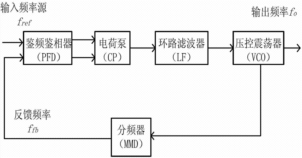
technical field [0001] The invention belongs to the field of electronic technology and relates to integrated circuit design technology, in particular to a charge pump circuit applied to a charge pump phase-locked loop. Background technique [0002] Phase-locked loop (PPL) is an important module in analog and digital-analog hybrid integrated circuits, and it is widely used in wireless communication, frequency synthesis, clock recovery, etc. Among various phase-locked loop structures, Charge Pump Phase-Locked Loop (CPPLL) is widely used in chip design because of its high stability, large capture range, and digital circuits for frequency and phase detectors. . [0003] A phase-locked loop is a feedback system that compares the phase of an input signal to an output signal. figure 1 Shown is a typical charge pump phase-locked loop system structure, including phase frequency detector (PFD), charge pump (CP), loop filter (LF), voltage controlled oscillator (VCO), frequency divide...

Claims


Application Information

Patent Timeline
IPC IPC(8): H02M3/07
CPCH03L7/0891H03L7/085
Inventor 方健贾姚瑶袁同伟潘华黄帅王贺龙
Owner UNIV OF ELECTRONIC SCI & TECH OF CHINA
Learn More