Multi-energy complementally driven dehumidification air-conditioning system

An air-conditioning system and complementary drive technology, applied in the field of dehumidification air-conditioning system and multi-energy complementary drive dehumidification air-conditioning system, can solve the problem of increasing the air to be treated, the negative impact on human health, increasing the area of ​​the gas-liquid contact area and the gas-liquid reaction time, etc. problems, to achieve the effect of increasing the contact area and contact time, significant social and economic benefits, and improving the efficiency of recycling.

Inactive Publication Date: 2013-04-17
SHANGHAI JIAO TONG UNIV +1
View PDF9 Cites 10 Cited by
  • Summary
  • Abstract
  • Description
  • Claims
  • Application Information

AI Technical Summary

Problems solved by technology

The Chinese patent (application) number is CN200820160676.7, and the name is solution dehumidification air-conditioning equipment using membrane regenerator, which discloses a solution dehumidification air-conditioning equipment using membrane regenerator. The solution regeneration of solution dehumidification air-conditioning equipment adopts ion exchange membrane , the positive and negative ions in the dilute solution are collected separately and mixed to form a new concentrated solution. The introduction of the ion exchange membrane realizes the regeneration of the dehumidification solution at room temperature, avoiding a large amount of energy loss caused by high temperature regeneration, but the regeneration of the dehumidification solution using the ion exchange membrane requires consumption Electric energy, and there is a great potential safety hazard
The Chinese patent (application) number is CN201010587750.5, and the name

Method used


Image

  • Multi-energy complementally driven dehumidification air-conditioning system

Examples


Embodiment Construction

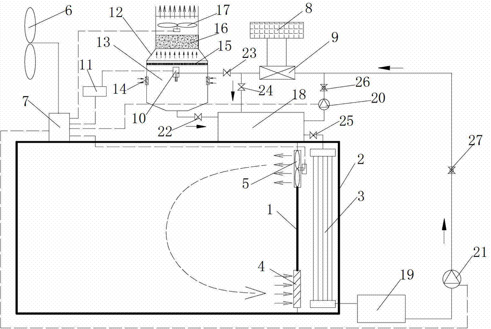
[0020] Such as figure 1 As shown, the present invention includes a partition wall 1 in a room, a body of wall 2 in a room, a hollow fiber membrane 3, an indoor return air outlet 4, an indoor circulation fan 5, a wind power generator 6, a storage battery 7, a solar heat collector 8, and a heat exchanger 9. Ultrasonic atomizer 10, ultrasonic generator 11, solution regenerator 12, accumulator 18, liquid collection pool 19, solution circulation pump 20, liquid return pump 21, A valve 22, B valve 23, C valve 24, D valve 25, E valve 26, F valve 27, wherein, the solution regenerator 12 is made up of atomizing chamber 13, air inlet 14, liquid baffle 15, demister 16 and exhaust fan 17.

[0021] The partition wall 1 in the room and the wall body 2 in the room form an air passage, and the hollow fiber silk membrane 3 is built in. There is an indoor return air outlet 4 under the partition wall 1 in the room, and an indoor circulation fan 5 is installed above the partition wall 1 in the ro...


PUM


Abstract

The invention discloses a multi-energy complementally driven dehumidification air-conditioning system which comprises a room internal partition wall, a room wall, a hollow fiber membrane, an indoor air return port, an indoor circulating fan, a wind driven generator, a storage battery, a solar thermal collector, a heat exchanger, an ultrasonic atomizer, an ultrasonic generator, a solution regenerator, an energy storage reservoir, a solution collection reservoir, a solution circulating pump, a liquid return pump and a plurality of valves. The solution regenerator is composed of an atomizing chamber, an air inlet, a solution baffle, a demister and an exhaust fan. The multi-energy complementally driven dehumidification air-conditioning system uses solar energy as the regeneration thermal source of a dehumidification solution, improves dehumidification solution regeneration efficiency by aid of the ultrasonic atomization effect, solves the problem of the solution dehumidification system that the air contains liquid by aid of the hollow fiber reverse osmosis membrane, is provided with electricity through wind power generation, and achieves diversification of system driving energy. The multi-energy complementally driven dehumidification air-conditioning system can meet architectural indoor dehumidification requirements in high-humidity seasons such as the spring and the summer, can supply heat to the buildings in summer, is especially suitable for being used in moist areas with cold winter and hot summer, and has remarkable social benefit and economic benefit.

Description

technical field [0001] The invention relates to a dehumidification air-conditioning system, in particular to a multi-energy complementary drive dehumidification air-conditioning system, which belongs to the technical field of building energy-saving engineering applications. Background technique [0002] The solution dehumidification technology uses a salt solution with dehumidification function (such as LiCl, CaCl2, LiBr, etc.) as the working medium, and uses the moisture absorption and dehumidification characteristics of the solution to adjust and control the air humidity. The water vapor partial pressure difference between the salt solution and the air is the driving force for water transfer between the two. When the surface vapor pressure of the solution is lower than the water vapor partial pressure in the air, the solution absorbs the water in the air and the air is dehumidified; otherwise, The moisture in the solution enters the air, the solution is concentrated and re...

Claims


Application Information

Patent Timeline
IPC IPC(8): F24F5/00F25B41/04F24F13/00
Inventor 姚晔陈静郭海新
Owner SHANGHAI JIAO TONG UNIV
Why Eureka
Try Eureka