Two-step oxidation-reduction flue gas denitration method

A flue gas and denitrification technology, applied in the field of flue gas denitrification, can solve the problems of high energy consumption, ammonia escape, ammonia leakage, etc., and achieve the effects of low investment and treatment cost, high ozone utilization rate, and broad application prospects.

Inactive Publication Date: 2013-04-24
ZHEJIANG GONGSHANG UNIVERSITY
View PDF11 Cites 12 Cited by
  • Summary
  • Abstract
  • Description
  • Claims
  • Application Information

AI Technical Summary

Problems solved by technology

with TiO 2 The main photocatalytic oxidation denitrification technology does not need to add additional oxidants, and has the advantages of mild reaction conditions, low energy consumption, and less secondary pollution. The efficiency for low-concentration NO can be as high as 90%, but for high-concentration NO removal less efficient
The traditional ozone oxidation method is to oxidize most of the NO in the flue gas into NO 2 After that, it can be absorbed with lye such as ammonia water, the effect is better, but the energy consumption is hi...

Method used


Image

  • Two-step oxidation-reduction flue gas denitration method

Examples


Embodiment 1

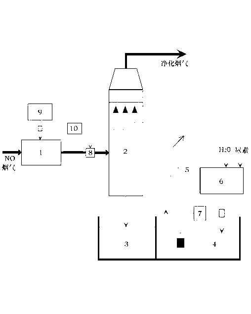
[0032] A company has a 10-ton heating chain furnace with a coal-fired flue gas volume of 33,000m 3 / h, the flue gas NO concentration is about 560mg / m 3 , the original flue gas denitrification system. The new denitrification design adopts the denitrification method of the present invention. The inner diameter of the reduction reaction tower is 1.5m, the height of the tower body is 10m, the material can be stainless steel, 3-layer spray is used, and the nozzle is a stainless steel spiral nozzle. The rated output of the ozone generator is 18kg / h, the inner diameter of the cylinder of the ozone oxidation device is 1.6m, and the length of the cylinder is controlled at 6m. The mass concentration of urea in the circulating reducing agent solution is 5%, and the operating water-gas ratio is 8L / m 3 , the aqueous solution is recycled, and the denitrification efficiency reaches 85.1% according to the test of the environmental protection monitoring department. The system is reliable in ...

Embodiment 2

[0034] A company has a 20-ton heating fluidized furnace with a coal-fired flue gas volume of 70,000m 3 / h, the flue gas NO concentration is about 460mg / m 3 , the original flue gas denitrification system. The new denitrification design adopts the denitrification method of the present invention. The inner diameter of the reduction reaction tower is 2.4m, and the height of the tower body is 12m. The rated output of the ozone generator is 28kg / h, the inner diameter of the cylinder of the ozone oxidation device is 2.2m, and the length of the cylinder is controlled at 8m. The mass concentration of urea in the circulating reducing agent solution is 4%, and the operating water-gas ratio is 10L / m 3 , the aqueous solution is recycled, and the denitrification efficiency reaches 83.2% according to the test of the environmental protection monitoring department. The system is reliable in operation, the denitrification effect is good, and the operating cost is low.


PUM

PropertyMeasurementUnit
Diameteraaaaaaaaaa
Efficiencyaaaaaaaaaa

Abstract

The invention discloses a two-step oxidation-reduction flue gas denitration method which comprises an ozone oxidation device 1, an ozone generator 9, an ozone adding control system 10, an NO/NOx sensor 8, a reduction reaction tower 2, an absorption liquid recovery pool 3, a reducing agent absorption liquid circulation pool, a reducing agent solution preparation device 6, a reducing agent solution adding device 7 and a circulating pump system 5. Firstly, flue gas to be treated enters the ozone oxidation device; under the action of ozone, part of NO in the flue gas is oxidated into NO2; afterwards, the flue gas is conveyed into the reduction reaction tower to be in contact with reducing agent solution; and under the action of reducing agents, most of NO and NO2 in the flue gas are reduced into N2, so that the purpose of denitration and purification of the flue gas can be achieved. Waste water generated after flue gas denitration reaction can be reclaimed and reused. The method provided by the invention accomplishes flue gas denitration in two steps, and has the advantages of high ozone utilization ratio, good denitration effect, recyclability of solution, low investment and treatment cost and broad application prospect.

Description

technical field [0001] The invention relates to a two-step oxidation-reduction flue gas denitrification method in the field of flue gas denitrification. Background technique [0002] Acid rain is one of the major environmental problems facing the contemporary world. According to statistics, my country's NO x The total annual discharge exceeds 20 million tons, which is one of the main causes of acid rain. NO x The pollution is serious and endangers the safety of the ecological environment. With the increasing power generation of coal-fired thermal power plants, the regional acid rain pollution in our country will tend to intensify. Coal combustion flue gas emission NO x It is one of the main sources of acid rain, and the denitrification of coal-fired flue gas has become the key to emission control. [0003] So far, coal-fired flue gas NO removal technologies mainly include selective catalytic reduction (SCR), non-selective catalytic reduction (SNCR), SNCR-SCR combined m...

Claims


Application Information

Patent Timeline
IPC IPC(8): B01D53/76B01D53/79B01D53/56
Inventor 李济吾
Owner ZHEJIANG GONGSHANG UNIVERSITY
Why Eureka
Try Eureka