Biological photometric device and biological photometry method using same

一种生物体、光测量的技术,应用在测量装置、使用光谱诊断、散射特性测量等方向,能够解决难以应用等问题,达到有效信号取得、避免测量点之间的干扰的效果

Active Publication Date: 2013-06-12
HITACHI HEALTHCARE MFG LTD
View PDF13 Cites 9 Cited by
  • Summary
  • Abstract
  • Description
  • Claims
  • Application Information

AI Technical Summary

Problems solved by technology

In situations where its assumptions do not hold, it is difficult to apply

Method used


Image

  • Biological photometric device and biological photometry method using same
  • Biological photometric device and biological photometry method using same
  • Biological photometric device and biological photometry method using same

Examples


Embodiment 1

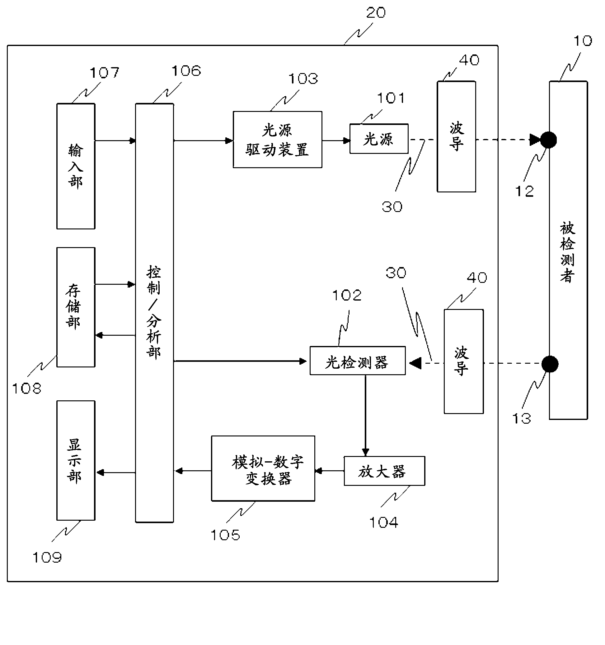
[0093] exist figure 1 In , an example of the device structure of the present invention is shown. In a biological light measurement device capable of detecting light that is incident on a living body, scattered, absorbed, and propagated in the living body, light 30 irradiated from one or more light sources 101 included in the device main body 20 is incident through a waveguide 40 to the subject 10. The light 30 is incident into the subject 10 from the irradiation point 12 , and after being transmitted and propagated in the subject 10 , it is detected by one or more light sources through the waveguide 40 from the detection point 13 located at a position separated from the irradiation point 12 . The device 102 detects. The SD distance is defined by the distance between the irradiation point 12 and the detection point 13 as described above.

[0094] Here, one or more light sources 101 can be semiconductor lasers (LDs), light emitting diodes (LEDs), etc., and one or more detecto...

Embodiment 2

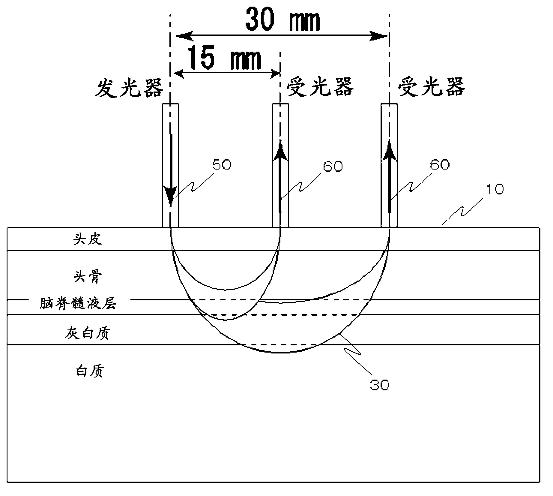
[0190] In Example 1, the distribution density of the measurement points at each SD distance may vary depending on the probe configuration. By adding only the photoreceiver 60 to the probe arrangement described in Embodiment 1, it is possible to easily increase the number of measurement points without lowering the time resolution. exist Figure 38 , indicating a 2x density probe configuration ( Figure 8 ) only the probe arrangement (a) and measurement point arrangement (b) of the photoreceiver 60 are added. For each light emitter 50 , a photoreceiver was added at a SD distance of 15 mm. At this time, if the measurement points with a SD distance of 15 mm exclude the measurement points related to the light emitters 50 on the upper and lower boundaries of the probe configuration, the number of light emitters 50 will double. The additional photoreceiver 60 receives light synchronously with at least one of the other plurality of photoreceptors 60, thereby increasing the number o...

Embodiment 3

[0194] exist Figure 39 In , a schematic diagram of a test using an optical brain function measurement device 90 of a head-to-head measurement type is shown. In the optical brain function measurement device 90, the head of the subject is irradiated with light belonging to wavelengths from visible light to the infrared region, and the light of signals of multiple wavelengths passing through the interior of the subject is detected by the same photodetector. And for measurement, the local cerebral blood volume (oxygenated hemoglobin / deoxygenated hemoglobin / total hemoglobin concentration length change) can be obtained. During the measurement period, appropriate stimuli / commands can also be given to the subject 10 through the stimulus / command presentation device 415 . Stimulus / command prompting device 415 is controlled by control signal 414 from computer 412 .

[0195] The following units are provided: modulators or oscillators 401a and 401b (401c and 401d), multiple light source...


PUM


Abstract

The present invention is capable of separating / removing the influence of skin blood flow contained in near infrared spectroscopy (NIRS) signals and extracting a brain- or brain cortex-origin signal. Moreover, the present invention enables versatile separation of brain-origin and skin-origin signals in view of differences among individuals. A biological photometric device, wherein light transmitters and light receivers are located in such a manner that measurement can be conducted at a plurality of source-detector (SD) distances and light received by the individual light-receivers can pass through the Grey substance to thereby separate a brain-origin signal and a skin-origin signal. Individual component analysis (ICA) is conducted on data obtained at the individual measurement points. Then, it is determined whether each individual component originates in the brain or in the skin with the use of the SD distance-dependency of the weighted value of each of the separated components.

Description

technical field [0001] The present invention relates to a technology for separating / removing the influence of surface components such as skin blood flow components mixed with signal components in a bio-optical measurement device using visible light or near-infrared light. Background technique [0002] Brain function measurement devices using near-infrared spectroscopy can be used as medical and research equipment, or for market research such as confirmation of educational effects and rehabilitation training effects, health management at home, and product monitoring. In addition, it can be used for tissue oxygen saturation measurement and muscle oxygen metabolism measurement by the same method. Furthermore, it can also be used for general absorption spectrometers including sugar content measurement of fruits. [0003] Optical topography (OT: Optical topography), which non-invasively images local blood dynamic changes near the surface of the human brain, is a brain function m...

Claims


Application Information

Patent Timeline
Patent Type & Authority Applications(China)
IPC IPC(8): A61B10/00A61B5/1455G01N21/17
CPCA61B5/0075A61B5/6814G01N21/359G01N21/49A61B5/0042A61B6/00
Inventor 舟根司敦森洋和桂卓成木口雅史高寺毅藤原伦行
Owner HITACHI HEALTHCARE MFG LTD
Why Eureka
Try Eureka