Method for prolonging service life of engine thermal barrier coating by controlling components of thermal growth oxide layer
A technology of thermally grown oxide layer and thermal barrier coating, applied in the direction of coating, metal material coating process, sustainable transportation, etc., can solve the problems of accelerated coating failure, affecting the continuity of thermally grown oxide layer, etc. The effect of extended service life
- Summary
- Abstract
- Description
- Claims
- Application Information
AI Technical Summary
Problems solved by technology
Method used
Image
Examples
Embodiment 1
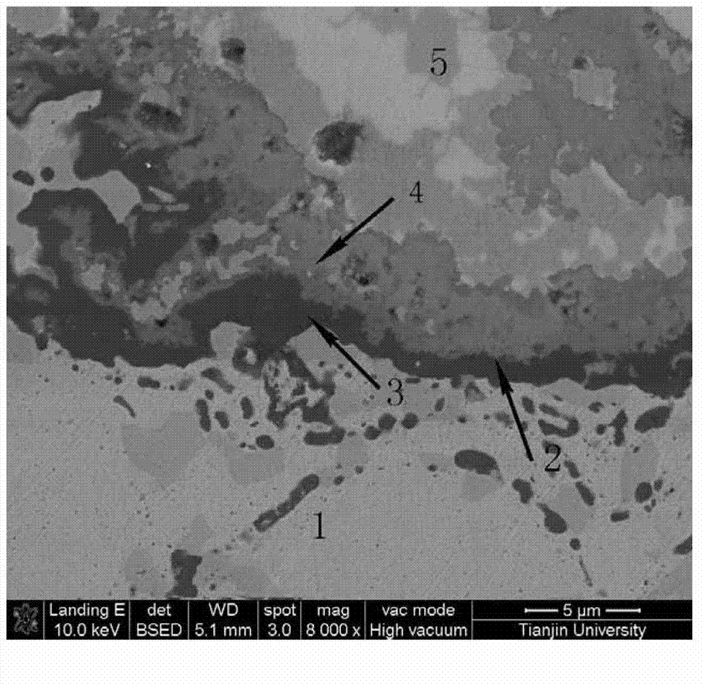
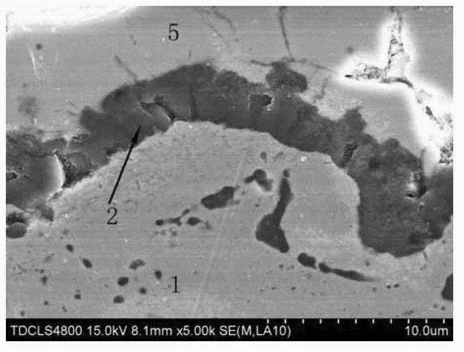
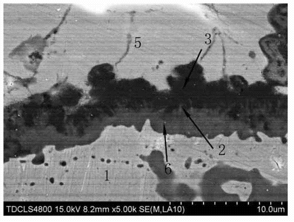
[0047] Clean the base alloy with a mixture of ethanol and acetone (1:1 volume ratio), and roughen the surface of the base alloy by sandblasting, and fully dry it. Then supersonic flame spraying is used to prepare a bonding layer with a thickness of 150 μm and a composition of Co-32Ni-21Cr-8Al-0.5Y on the base alloy. The process parameters are: O 2 Air pressure and flow are 0.7MPa and 12m respectively 3 / h, propane gas pressure and flow are 0.6MPa and 1.0m respectively 3 / h, powder feeding gas N 2 The pressure and flow are 0.6MPa and 0.96m respectively 3 / h, the powder feeding amount is 35g / min, and the spraying distance is 300mm. Subsequent atmospheric plasma spraying of the ceramic layer ZrO 2 -8%Y 2 o 3 (wt.%), the thickness is 200μm, the process parameters are: spraying power is 42Kw, spraying voltage is 70V, spraying current is 600A, powder feeding rate is 35g / min, gun speed is 500mm / s, Ar gas pressure and flow rate respectively 0.6MPa and 40L / min, H 2 The air pres...
Embodiment 2
[0048] Example 2: The thermal spraying parameters used in preparing the thermal barrier coating in this example are the same as those in Example 1.
[0049] The process parameters of the vacuum heat treatment are also the same as those in Example 1, but heated to 1000° C. in the air environment, and heat-preserved and diffused for 10 hours. The thermal barrier coating sample prepared by the present invention is subjected to thermal shock, and the thermal shock process parameters are the same as in Example 1, and are the same as those in Example 1. Figure 4 and Figure 5 compared to, Image 6 After 100 thermal shocks of the coating, the peeling degree was further reduced.
Embodiment 3
[0050] Example 3: The thermal spraying parameters used in the preparation of the thermal barrier coating in this example are the same as those in Example 1.
[0051] The process parameters of the vacuum heat treatment are also the same as those in Example 1, but heated to 1100° C. in the air environment, and heat-preserved and diffused for 10 hours. The thermal barrier coating sample prepared by the present invention is subjected to thermal shock, and the thermal shock process parameters are the same as in Example 1, and are the same as those in Example 1. Figure 4 , Figure 5 with Image 6 compared to, Figure 7 After 100 times of thermal shock, the degree of spalling of the coating is the lowest.
PUM
 Abstract
Description
Claims
Application Information
 - R&D
- Intellectual Property
- Life Sciences
- Materials
- Tech Scout
- Unparalleled Data Quality
- Higher Quality Content
- 60% Fewer Hallucinations
Browse by: Latest US Patents, China's latest patents, Technical Efficacy Thesaurus, Application Domain, Technology Topic, Popular Technical Reports.
© 2025 PatSnap. All rights reserved.Legal|Privacy policy|Modern Slavery Act Transparency Statement|Sitemap|About US| Contact US: help@patsnap.com


