Device and method for waste gas photocatalytic degradation using electrodeless excimer lamp
A catalytic degradation and excimer technology, which is applied in the field of devices for catalytic degradation of waste gas by non-polar excimer light, can solve the problems of small selection range of electrode materials and luminescent substances, long ignition time and stabilization time, and low utilization rate of light radiation. Avoid electrode aging, occupy a small area, and have a wide range of applications
- Summary
- Abstract
- Description
- Claims
- Application Information
AI Technical Summary
Problems solved by technology
Method used
Image
Examples
Embodiment 1
[0056] (Example 1, a device for catalytically degrading exhaust gas by non-polar excimer lights)
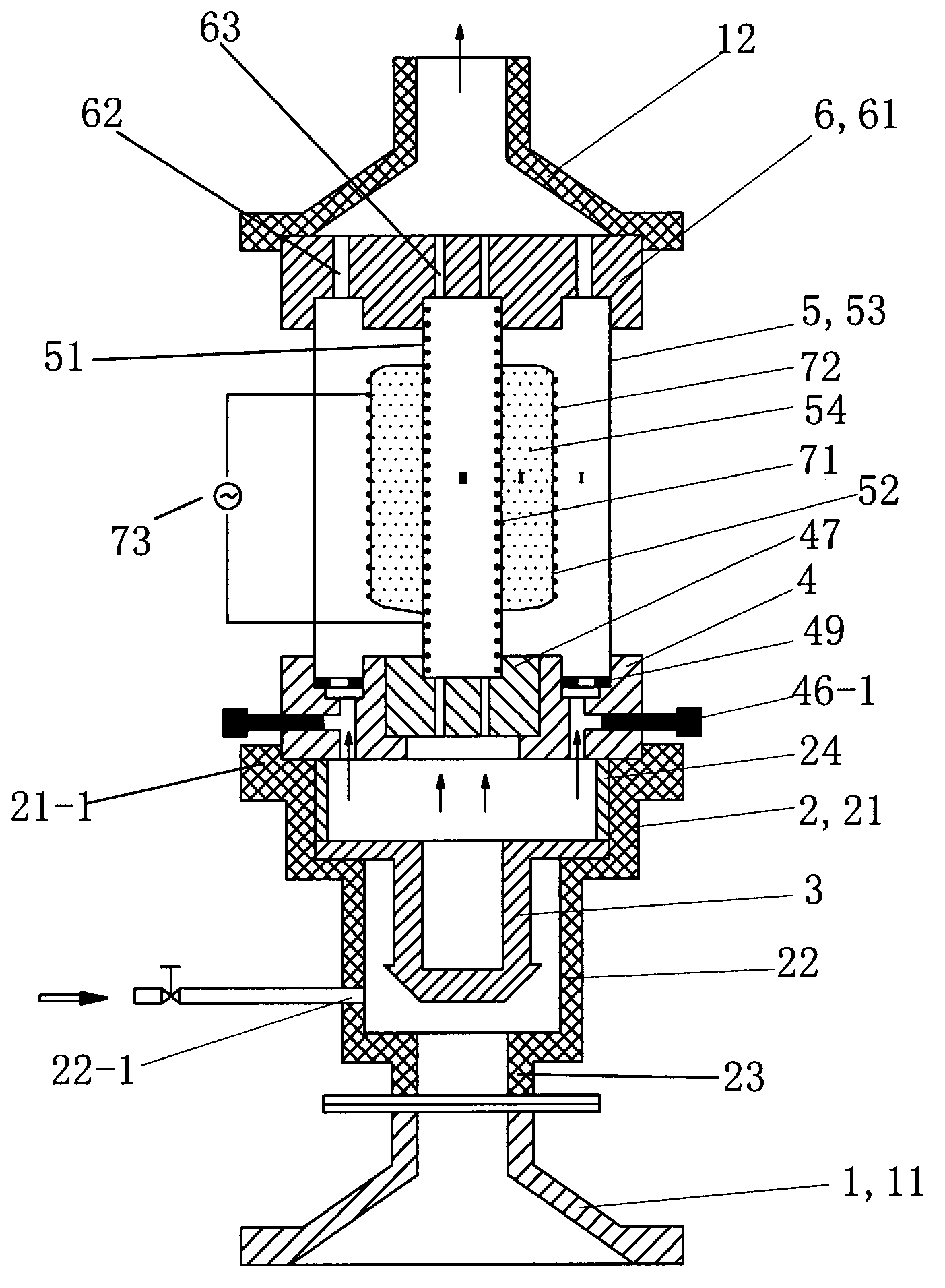
[0057] See figure 1 , The device of the present embodiment of the non-polar excimer light catalytic degradation of exhaust gas includes a gas collection hood 1, a connecting sleeve 2, a gas mixer 3, an inlet distributor 4, a reactor 5, an outlet distributor 6 and an induced draft fan. The air collecting hood 1 includes a lower air collecting hood 11 and an upper air collecting hood 12 . The lower gas collecting hood 11, the gas mixer 3, the reactor 5, the gas outlet distributor 6 and the upper gas collecting hood 12 are arranged sequentially from bottom to top.
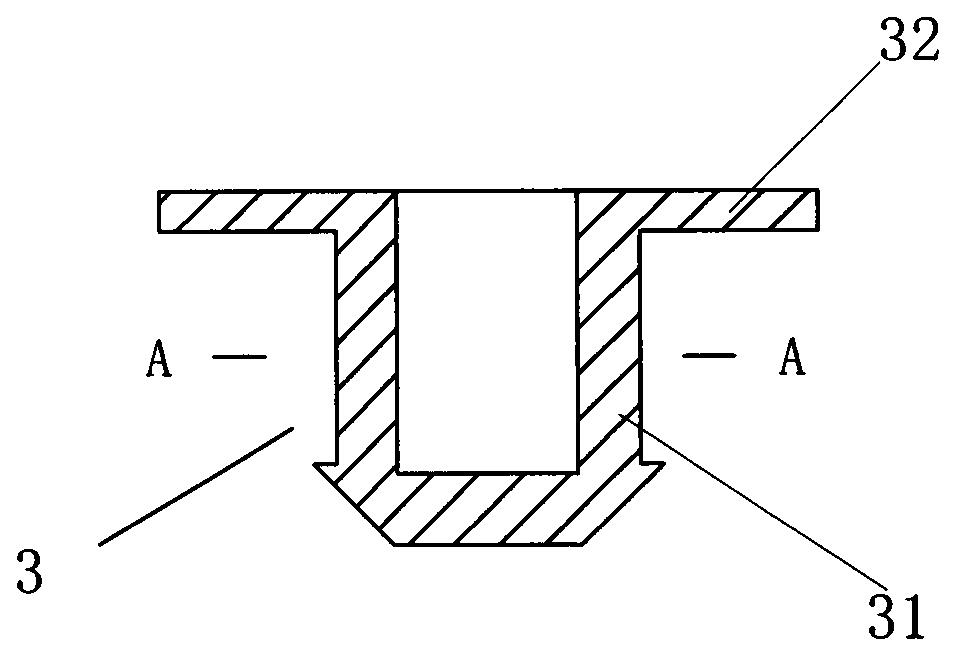
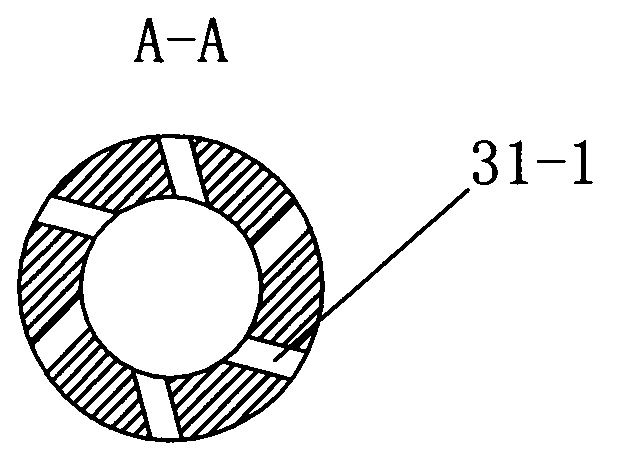
[0058] The air inlet of the lower gas collecting hood 11 is connected with the exhaust gas generator gas outlet or the gas storage tank of the gas to be degraded, and the gas outlet of the lower gas collecting hood 11 is connected with the air inlet of the connecting sleeve 2 through a flange. The gas mixer 3 is arran...
Embodiment 2
[0093] (Example 2, the method of non-polar excimer light catalytic degradation exhaust gas)
[0094] The method for catalytically degrading waste gas by light-emitting excimer light in this embodiment adopts the device described in Embodiment 1, and the through-hole plug used in the air inlet distributor 4 is a blind hole plug 48 . The inner electrode 71 is made of metal sheet, and the outer electrode 72 is made of metal mesh.
[0095] The process of photocatalytic degradation of waste gas by non-polar excimer lights is as follows: the waste gas from the waste gas generator or the waste gas storage tank is initially mixed by the gas mixer 3, and then further mixed evenly by the air inlet distributor 4, and then enters the reactor under the action of the induced draft fan 5 for purification. The outlet of the reactor 5 is 1m away from the reactor, and a sampling port is set, and the concentration of the reacted gas is detected by an online gas analyzer, and the gas degraded to...
Embodiment 3
[0102] (Example 3, the method of non-polar excimer light catalytic degradation of waste gas)
[0103] The method for catalytically degrading waste gas by light-emitting excimer light in this embodiment adopts the device described in Embodiment 1, and the through-hole plug used in the air inlet distributor 4 is a porous plug 47 . The inner electrode 71 is made of metal mesh, and the outer electrode 72 is made of metal sheet.
[0104] See Figure 7 , in this example, the degradation flow dynamics simulates dimethylamine waste gas, and the initial concentration is 3745mg / m 3 , the method for degrading exhaust gas specifically includes the following steps:
[0105] ①Evacuate the gas-filled zone II, and then fill it with Kr:Cl 2 =350:1, total pressure 205torr.
[0106]② Turn on the high-voltage power supply 73, apply an external voltage of 6kV, and a power of 50W. The gas-filled mixed gas in zone II is excited to generate excimer ultraviolet light to radiate to the reaction zon...
PUM
 Abstract
Description
Claims
Application Information
 - R&D
- Intellectual Property
- Life Sciences
- Materials
- Tech Scout
- Unparalleled Data Quality
- Higher Quality Content
- 60% Fewer Hallucinations
Browse by: Latest US Patents, China's latest patents, Technical Efficacy Thesaurus, Application Domain, Technology Topic, Popular Technical Reports.
© 2025 PatSnap. All rights reserved.Legal|Privacy policy|Modern Slavery Act Transparency Statement|Sitemap|About US| Contact US: help@patsnap.com


