System for producing clean energy

A clean energy and gasification device technology, applied in the system field of clean energy production, can solve problems such as impact, ecological system life hazard, ecosystem damage, etc., and achieve the effects of increasing economic benefits, reducing product costs, and improving thermal efficiency

Active Publication Date: 2013-07-17
SHIJIAZHUANG XINHUA IND FURNACE CO LTD
View PDF4 Cites 13 Cited by
  • Summary
  • Abstract
  • Description
  • Claims
  • Application Information

AI Technical Summary

Problems solved by technology

[0002] Environmental pollution will cause direct damage and impact on the ecosystem, and also cause great harm to the ecosystem and people's lives

Method used


Image

  • System for producing clean energy
  • System for producing clean energy
  • System for producing clean energy

Examples


Embodiment 1

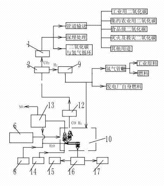
[0023] The system of clean energy production of the present invention is as figure 1 As shown, it includes gasification device 10, coal stockyard 6, shift reaction and hydrogen purification device 2, gas purification device 12, hydrogen delivery equipment 9, carbon dioxide storage device 1, nitrogen oxide compound treatment and water vapor recovery device 13, water vapor storage tank 8 , oxygen and oxygen-enriched air supply equipment 14 , heavy metal treatment equipment 15 , slag separation equipment 16 , cement plant 17 and water vapor storage tank 8 . The gasification device is provided with feeding equipment 21, gasification equipment, fuel gas inlet, steam inlet, flue gas outlet, gasification gas outlet and waste residue outlet. The feeding equipment is connected with the coal yard, and the steam inlet is connected with the steam storage tank. The conversion reaction and hydrogen purification device is provided with a gas inlet, a hydrogen outlet and a carbon dioxide out...

Embodiment 2

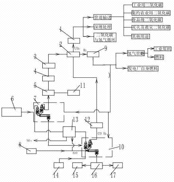
[0026] Another embodiment of the present invention is as figure 2 As shown, the clean energy production system also includes a coking unit 7 , a cracking unit 3 , a gas purification unit 4 , a tar separation unit 5 and a tar and chemical utilization unit 11 . The coking device is provided with feeding equipment 21, flue gas outlet, fuel gas inlet, pulverized coal nozzle, coking gas outlet and coke outlet. The feeding equipment is connected to the coal stockyard 6, the coke outlet is connected to the feeding equipment of the gasification device 10, the coking gas outlet is connected to the tar separation device 5, and the flue gas outlet is connected to the flue gas of the nitrogen oxide treatment and water vapor recovery device 13. The gas inlet and the fuel gas inlet are connected with the hydrogen delivery equipment 9 . The tar separation device is provided with a liquid outlet and a gas outlet, the liquid outlet is connected to the tar and chemical utilization device 11, ...

Embodiment 3

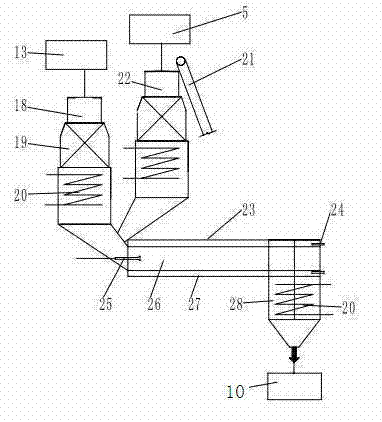
[0029] Another form of the gasification device of the clean energy production system of the present invention is as Figure 5 As shown, a common rotary kiln 32, a cooler 28 and a raw material preheater 22 are provided. Common rotary kiln is provided with hydrogen and oxygen nozzle 31. The raw material preheater 22 is provided with a heat exchanger 19, a power generation steam coil 20, an upper port, a lower port and a gasification outlet. The upper port is connected to the feeding equipment 21, the lower port is connected to the kiln chamber of a common rotary kiln, and the gasification outlet is connected to the gas purification device 12. The cooler is provided with a power generation steam coil 20, the upper port of the cooler is connected with a common rotary kiln, and the lower port is connected with a slag separation device 16. Other processes and equipment are the same as in Example 1.


PUM


Abstract

The invention relates to a system for producing a clean energy. The system comprises a gasification device, a coking device, a shift reaction and hydrogen purification device, a gas purification device, hydrogen transporting equipment, a carbon dioxide storage device, an oxynitride treatment and water vapour recycling device, oxygen and oxygen-enriched air supplying equipment, heavy metal treatment equipment, slag separation equipment, a cement plant, a coal material plant and a water vapor storage tank. Due to the arrangement of the gas purification device, the shift reaction and hydrogen purification device, a coal tar separation device, a cracking device and a coal gas purification device, the coal gas generated by coal gasification and coking is purified and converted into the hydrogen, thereby providing the valuable clean energy. The hydrogen serves as a heating fuel for the whole system, so that the carbon dioxide is not generated during the combustion process in the heating manner; and the fuel gas generated by the combustion is discharged after oxynitrides in the fuel gas are removed. Therefore, pollutants are reduced and avoided being generated and diffused. By utilizing a wall-dividing-type rotary kiln, the fuel gas generated by the combustion is prevented from polluting, coking and gasifying products.

Description

technical field [0001] The invention belongs to the technical field of clean energy production and environmental protection, and relates to a clean energy production system. Background technique [0002] Environmental pollution will not only cause direct damage and impact to the ecosystem, but also cause great harm to the ecosystem and people's lives. The most direct and easily felt consequence of environmental pollution is to reduce the quality of the human environment and affect the quality of life, health and production activities of human beings. For example, urban air pollution causes air pollution, and people's morbidity rate increases; water pollution deteriorates the quality of water environment, and the quality of drinking water sources generally declines, threatening people's health, causing premature birth or deformity of fetuses, etc. Serious pollution incidents not only bring health problems, but also social problems. With the intensification of pollution and ...

Claims


Application Information

Patent Timeline
Patent Type & Authority Applications(China)
IPC IPC(8): C10J3/00C10J3/84C10J3/80C10J3/74C10J3/72C10B53/08C10B15/00C10B53/04C10B57/00C10B47/00C01B3/02C01B3/22C01B3/12C01B3/50C01B31/20C04B7/24C01B32/50
CPCY02P30/00Y02P40/10Y02P40/18
Inventor 贾会平
Owner SHIJIAZHUANG XINHUA IND FURNACE CO LTD
Why Eureka
Try Eureka