Waveguide direct-feed-type microwave plasma torch device
A microwave plasma and direct-feed technology, applied in the field of chemical measurement, can solve problems such as the limitation of coaxial cable bearing capacity, achieve the effect of improving microwave coupling efficiency and simplifying the complexity
- Summary
- Abstract
- Description
- Claims
- Application Information
AI Technical Summary
Problems solved by technology
Method used
Image
Examples
Embodiment 1
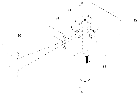
[0048] see figure 1 , a waveguide direct-fed microwave plasma torch device, the device is mainly composed of a waveguide part, a tuning and auxiliary part, and a coaxial torch tube part.
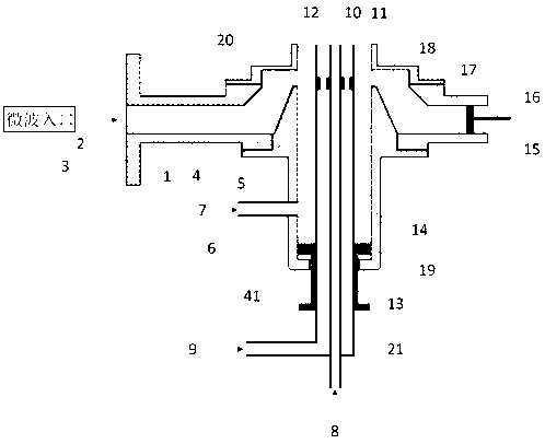
[0049] see figure 2 , a schematic side-view profile of the main part of the waveguide direct-fed microwave plasma torch, where
[0050] The waveguide part includes a tapered waveguide 30 and a narrow-side compression waveguide 31, wherein the narrow-side compression waveguide 31 and the matched MPT three-tube coaxial torch 32 constitute the main part of the waveguide direct-fed MPT, and the narrow-side compression waveguide 31 is Microwaves are fed into the main body waveguide.
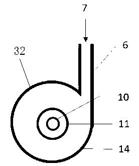
[0051] see image 3 , The coaxial torch 32 part includes the outer tube 14, the middle tube 11, the inner tube 10, the adjusting stud 13 and the coaxial centering washer 12, and the three tubes are in a coaxial structure. The inner diameter of the outer tube 14 is preferably 20-28 mm, the outer diameter of the...
Embodiment 2
[0069] see Figure 6 , Figure 7 , a simulation of electromagnetic field distribution in a waveguide-fed microwave plasma torch device. The simulation results are helpful to understand the working mechanism of this structure. The structure and dimensions of the device used are as described in Example 1.
[0070] Figure 6 This is the simulated diagram of the electromagnetic field distribution of the waveguide part in this example, and the simulated microwave frequency is 2450 MHz. The three sections of waveguides are BJ26, tapered waveguide 30 and narrow-side compressed waveguide 31 respectively. Microwaves are introduced from the left side of the BJ26 waveguide, transmitted to the short-circuit end on the right side of the narrow-side compression waveguide 31 and reflected back, thereby forming a standing wave field inside the waveguide. It can be seen from the figure that the electric field strength gradually becomes stronger from left to right, and is coupled into the ...
Embodiment 3
[0073] Figure 8 It is a diagram of the actual working state of the waveguide direct-fed MPT device designed based on the present invention. The structure and dimensions of the device used are as described in Example 1. The experimental conditions are as follows:
[0074] A magnetron is used as a microwave transmitting device, the output power is continuously adjustable from 100W to 1500W, and the device works at a power of 1000W. The carrier gas and maintenance gas fed into the middle tube 11 and the inner tube 10 are both argon with a purity of 99.999% and a gas flow >1.2 L / min. Oxygen shielding gas is introduced between the outer pipe 14 and the middle pipe 11 to shield the air in the environment, the purity is 99.999%, and the air flow is 1.5 L / min. The formed argon plasma flame 36 is as Figure 8 shown.
[0075] Figure 9 Schematic diagram of the structure of the argon plasma flame 36 formed by the waveguide direct-fed microwave plasma torch. The formed plasma con...
PUM
 Abstract
Description
Claims
Application Information
 - R&D
- Intellectual Property
- Life Sciences
- Materials
- Tech Scout
- Unparalleled Data Quality
- Higher Quality Content
- 60% Fewer Hallucinations
Browse by: Latest US Patents, China's latest patents, Technical Efficacy Thesaurus, Application Domain, Technology Topic, Popular Technical Reports.
© 2025 PatSnap. All rights reserved.Legal|Privacy policy|Modern Slavery Act Transparency Statement|Sitemap|About US| Contact US: help@patsnap.com


