Flue gas desulphurization device and desulphurization method

A technology of a dosing device and a dehydrator, which is applied in separation methods, chemical instruments and methods, and dispersed particle separation, etc., can solve the problems of high labor intensity in operation and inspection, low space utilization rate, and reduced energy consumption of flue gas desulfurization devices.

Inactive Publication Date: 2013-09-04
杭州蓝轩环保科技有限公司
View PDF6 Cites 2 Cited by
  • Summary
  • Abstract
  • Description
  • Claims
  • Application Information

AI Technical Summary

Problems solved by technology

[0003] The technical problem to be solved by the present invention is to provide a flue gas desulfurization device and a desulfurization method, which overcomes the shortcomings of traditional flue gas desulfurization devices, such as large factory area, low space utilization rate, high investment in engineering construction, and high labor intensity for equipment operation and inspection. , while significantly reducing the energy consumption of the flue gas desulfurization unit

Method used


Image

  • Flue gas desulphurization device and desulphurization method
  • Flue gas desulphurization device and desulphurization method
  • Flue gas desulphurization device and desulphurization method

Examples


Embodiment 1

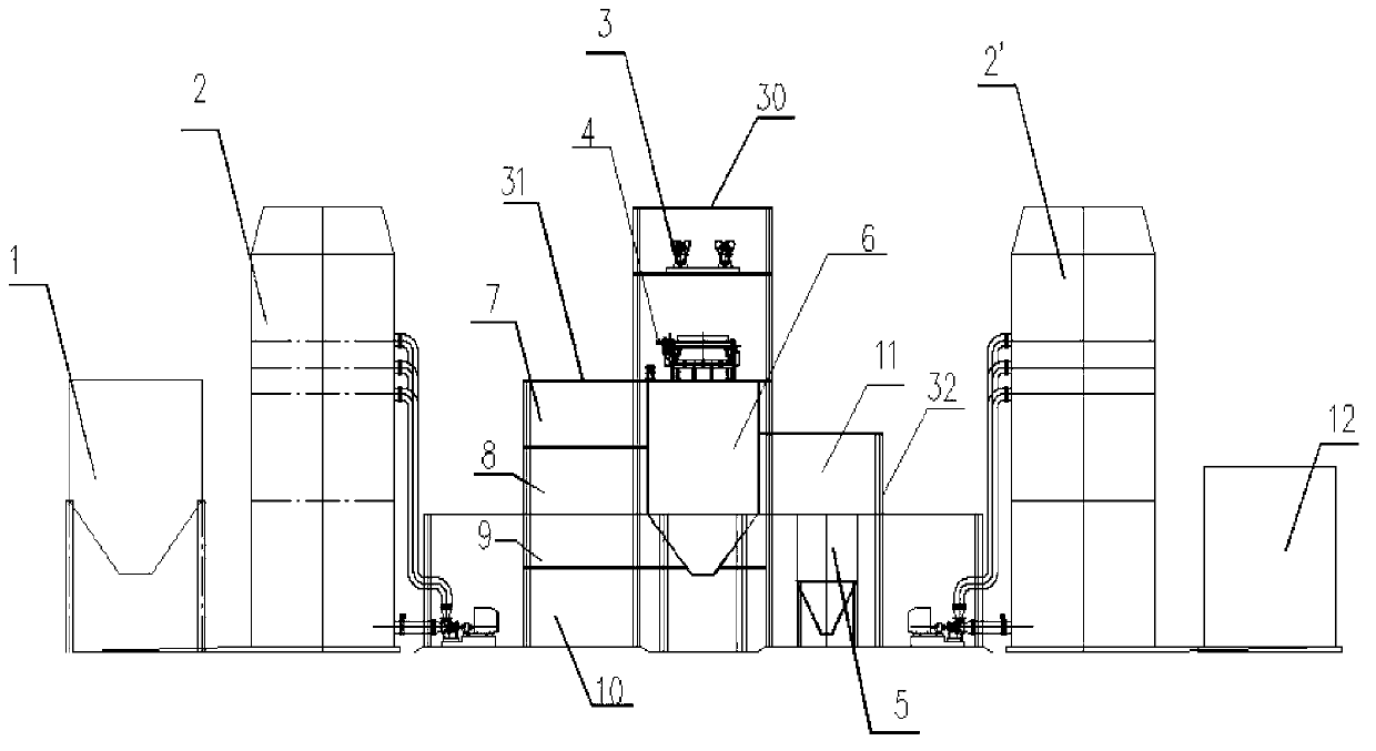
[0024] Such as figure 1 The flue gas desulfurization device of the present invention includes a limestone slurry preparation system, a flue gas absorption system, a gypsum slurry dehydration system, a waste water treatment system and an electric control system; it is three-dimensionally arranged in the process complex building and on the ground around it.

[0025] The limestone slurry preparation system includes a limestone powder bin 1, a limestone slurry preparation tank and a limestone slurry transfer pump.

[0026] The flue gas absorption system includes an absorption tower circulating pump, an oxidation fan, No. 1 absorption tower 2, No. 2 absorption 2', a gypsum slurry discharge pump, and an accident slurry tank 12.

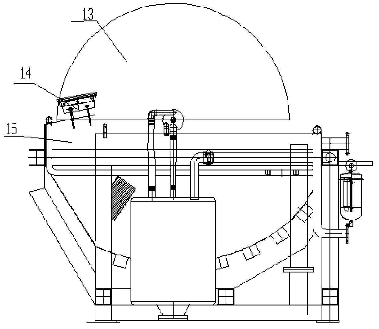
[0027] The gypsum slurry dewatering system includes a gypsum cyclone 3, a disc dehydrator 4, and a gypsum storage bin 6; the gypsum cyclone 3, a disc dehydrator 4, and a gypsum storage bin 6 are free from space. The gypsum cyclone 3 is located at the top end, the ...

Embodiment 2

[0037] Such as figure 1 As shown, the absorbent used in the flue gas desulfurization device of the present invention—limestone powder is transported to the power plant by a transport vehicle. The limestone powder silo 1 is unloaded by the transport vehicle. The limestone powder stored in the limestone powder silo 1 is prepared by adding water to form a limestone slurry , Use the limestone slurry transfer pump to send the limestone slurry into the No. 1 absorption tower 2 and the No. 2 absorption tower 2'. The limestone slurry is sprayed by the absorption tower circulation pump to realize the sulfur-containing boiler flue gas in the No. 1 absorption tower 2, 2 The reaction absorption in No. 2 absorption tower, the limestone slurry after the reaction is completed to form a gypsum slurry, and the oxidation fan is used to blow air into the absorption tower, so that the desulfurization reaction can be fully carried out. The accident slurry tank 12 is used for the storage of gypsum sl...


PUM


Abstract

The invention provides a flue gas desulphurization device and desulphurization method. The flue gas desulphurization device comprises a limestone slurry preparation system, a flue gas absorption system, a gypsum slurry dehydration system, a waste water treatment system and an electronic control system. According to the flue gas desulphurization device, flue gas important parts, namely a gypsum slurry dehydration system taking a disc type dehydrator as a core, the waste water treatment system and the electronic control system, are integrated and three-dimensionally arranged in one technology comprehensive building, other technological stages in flue gas desulphurization are arranged on ground at the periphery of the technology comprehensive building tightly around the technology comprehensive building, structure is compact, layout is reasonable, space resource is fully utilized, floor space is saved, labour intensity in equipment running check is reduced, engineering construction investment is saved, and energy consumption of the flue gas desulphurization device is greatly reduced.

Description

Technical field [0001] The invention relates to the technical field of wet flue gas desulfurization, in particular to a flue gas desulfurization device and a desulfurization method. Background technique [0002] At present, thermal power generation accounts for more than 80% of the total power generation, and the thermal power industry's sulfur dioxide emissions account for more than 40% of the total emissions. Controlling thermal power sulfur dioxide emissions is of great significance to the stricter energy conservation and environmental protection requirements. The limestone-gypsum wet flue gas desulfurization (WFGD) process is currently the main process for desulfurization in thermal power plants. The wet flue gas desulfurization process desulfurizes the sulfur dioxide and limestone slurry in the absorption tower to form the desulfurization by-product gypsum slurry, and then removes the excess water in the gypsum slurry through the gypsum dehydration system to make gypsum with...

Claims


Application Information

Patent Timeline
Patent Type & Authority Applications(China)
IPC IPC(8): B01D53/78B01D53/50
Inventor 陈扬
Owner 杭州蓝轩环保科技有限公司
Why Eureka
Try Eureka