Gate-type double-tower gear-driven drilling machine

A door type, drilling rig technology, applied in the direction of rotary drilling rig, drill pipe, drill pipe, etc., can solve the problems of a large amount of power consumption friction resistance, slow drilling speed, drilling efficiency discount, etc., to improve operation and mechanical efficiency, start-up And the effect of small stopping inertia and reasonable installation and disassembly design

Inactive Publication Date: 2013-09-11
SHAANXI XINLONG PETROLEUM EQUIP
View PDF5 Cites 5 Cited by
  • Summary
  • Abstract
  • Description
  • Claims
  • Application Information

AI Technical Summary

Problems solved by technology

[0003] 1. The mechanical efficiency is low, and a large amount of power is consumed in the friction resistance of the dynamic and static pulleys;
[0004] 2. The winch needs to be used as a counterweight to meet the maximum tension of the fast rope, which not only consumes a lot of steel, but also brings difficulties to moving and transportation;
[0005] 3. The structure of the pulley block and the swimming system is complicated, and it needs to be disassembled and assembled repeatedly every time it is transported, and the dead rope end of the winch drum needs to be cut off every time it is transported. If the length of the dead rope end is not enough, the entire drilling rope will be scrapped, which is a serious waste;
[0006] 4. The floating crane system is a flexible connection, which cannot be effectively fixed. When the drill is tripped, it will swing greatly and may hit the derrick, which will bring hidden dangers to safe production;
[0007] 5. The steel wire rope is easy to be impacted, squeezed and subjected to complicated forces during transportation and drilling, and is

Method used


Image

  • Gate-type double-tower gear-driven drilling machine
  • Gate-type double-tower gear-driven drilling machine
  • Gate-type double-tower gear-driven drilling machine

Examples


Example Embodiment

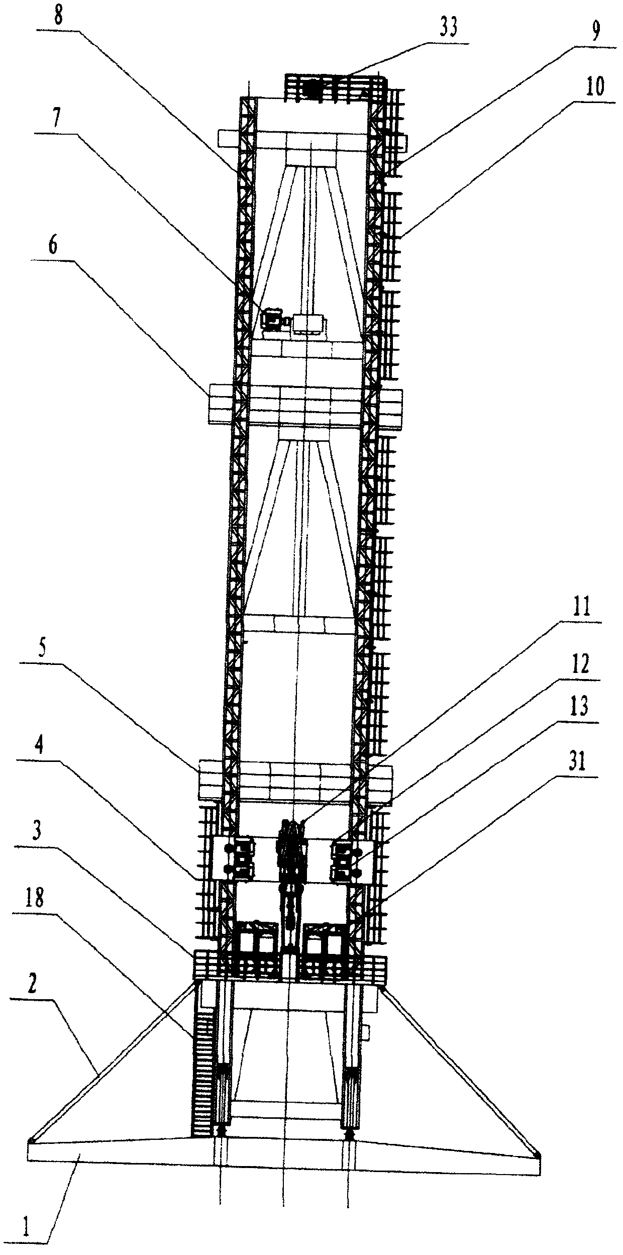
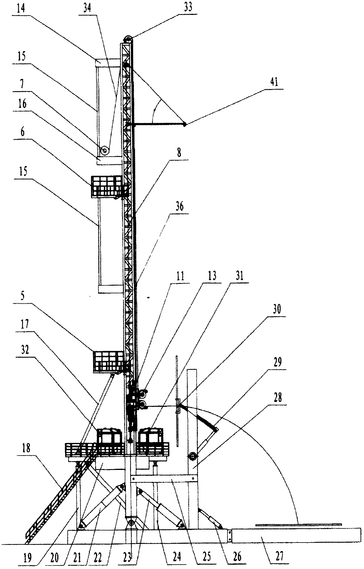
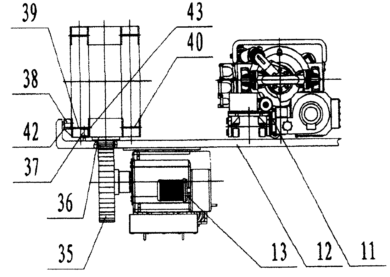
[0033] The content of the present invention will be further described below in conjunction with the drawings, but the actual application form of the present invention is not limited to the following embodiments.

[0034] Referring to the drawings, the gate-type double-tower-tooth drive drilling rig according to the present invention includes a derrick, a base, a top drive 11, a top drive block 12, a single drill pipe two-layer platform 5, and a double-root (vertical) drill pipe two-layer platform 6 , Quick trip device, up-and-off device, drill pipe 30, drill pipe transfer device 29, chuck, drill pipe transfer control system 31, driller control system 32, derrick and base lifting system and other parts. The base of the derrick is composed of bottom layer 1, struts 2, inclined ladder 18, straight struts 19, upper layer 20, diagonal struts 22, straight struts 24, pipe grabber beam 25 and pipe grabber bracket 28. The main body of the derrick is vertically mounted on the bottom layer ...


PUM


Abstract

The invention relates to a gate-type double-tower gear-driven drilling machine. A headframe body assembled on a base comprises two parallel single-gate-post towers, a racking platform provided with a single drill rod and a racking platform provided with double drill rods are arranged in the middle of the headframe, a vertical rack track is arranged in the position of a side surface of a headframe, and a fast trip device comprises a pulley block arranged at the top of the headframe, a steel wire rope and a fast trip winch; a top drive of the drilling machine is arranged on a top drive pulley where a motor and a suspension device are mounted; the suspension device of the top drive pulley is connected with the steel wire rope of the fast trip device; an output shaft of the motor on the top drive pulley is meshed with the vertical rack track through a gear; and a drill rod moving device is mounted on the headframe or the base in a hinging manner. During working, the suspension can rapidly release the top drive under the drive of the trip winch, so that rapid conversion of well repairing, drilling and forcibly tripping operation of a tubular column is realized, and requirements of no-load/light-load rapid tripping operation when the drilling machine drills a deep well are met.

Description

technical field [0001] The content of the present invention belongs to the technical field of petroleum drilling rig equipment, and relates to a portal-type double-tooth tooth-driven drilling rig suitable for drilling and drilling in industries such as geology, exploration, coal fields, municipal administration, water wells, and horizontal crossing. Background technique [0002] The equipment known both at home and abroad to be used for drilling, perforating operation is mostly the rig that adopts winch, traveling block, crown block and wire rope swimming system as the main mode of tripping operation. With the increasing demand for energy worldwide and the continuous improvement of the automation level of drilling rig components, this kind of drilling rig equipment has many shortcomings in coping with complex and specific geological conditions and operating efficiency, energy saving and environmental protection, cost performance, and reliability. Well team and user requireme...

Claims


Application Information

Patent Timeline
IPC IPC(8): E21B3/02E21B15/00E21B19/00
Inventor 畅宁傅建玮
Owner SHAANXI XINLONG PETROLEUM EQUIP
Why Eureka
Try Eureka