Non-contact remote water level detecting method based on chaos laser

A chaotic laser, water level detection technology, applied in measurement devices, engine lubrication, liquid/fluid solid measurement, etc., can solve the problems of poor stability of commercial MODEM, high price of MODEM, unstable wireless signal, etc. Low power consumption and flat power spectrum

Active Publication Date: 2013-09-18
TAIYUAN UNIV OF TECH
View PDF8 Cites 9 Cited by
  • Summary
  • Abstract
  • Description
  • Claims
  • Application Information

AI Technical Summary

Problems solved by technology

Wireless communication needs to establish signal relay stations on high mountains and beside rivers, so the investment is very large. Moreover, general wireless signals are unstable and easy to be interfered. In severe cases, signal interruptions are caused, and cascaded wireless transmission networks are often required.
Wired communication often adopts PSTN network, using MODEM communication,

Method used


Image

  • Non-contact remote water level detecting method based on chaos laser

Examples


Embodiment approach 1

[0023] To implement a non-contact remote water level detection method based on chaotic laser provided by the present invention, the specific implementation method is as follows:

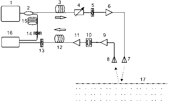
[0024] An ultra-wideband chaotic laser source 1 is provided, and the ultra-wideband chaotic laser generated by the chaotic laser source 1 is divided into probe light and reference light through the fiber coupler 2; wherein, the probe light passes through the first single-mode fiber 3 to the optically adjustable attenuation The detection light power is controlled by the first photodetector 4, and then converted into a corresponding electrical signal by the first photodetector 5. The electrical signal is amplified by the first low-noise amplifier 6 and then transmitted by the ultra-wideband transmitting antenna 7; The broadband receiving antenna 8 receives the partially reflected signal from the liquid surface 17, and then is amplified by the second low-noise amplifier 9 and linearly modulates the output o...

Embodiment approach 2

[0028] To implement the non-contact remote water level detection method based on chaotic lasers of the present invention, firstly, a central station, a transmission fiber and a remote antenna terminal are set up. Wherein, the central station includes an ultra-wideband chaotic laser source 1, a fiber coupler 2, a third single-mode fiber 15, a third photodetector 14, a second photodetector 13, and a data processing center 16. The transmission fiber It includes a first single-mode fiber 3 and a second single-mode fiber 12; the remote antenna end includes an optical tunable attenuator 4, a first photodetector 5, a first low-noise amplifier 6, an ultra-wideband transmitting antenna 7, An ultra-wideband receiving antenna 8, a second low-noise amplifier 9, a semiconductor laser 10, and an optical amplifier 11.

[0029] First, the ultra-wideband chaotic signal generated by the ultra-wideband chaotic laser source 1 is used as the detection signal, which is divided into the detection signa...


PUM

PropertyMeasurementUnit
Bandwidthaaaaaaaaaa

Abstract

The invention provides a non-contact remote water level detecting method based on chaos laser, which is characterized in that an ultra wide band chaos signal serves as a detection signal and reaches a remote antenna terminal after being transmitted by long single mode optical fiber to be transformed into a corresponding electrical signal to be emitted by an ultra wide band antenna, the detection signal is received by an ultra wide band antenna of the same type after being partially reflected at the water level, after a laser is linearly modulated, the electrical signal is transformed into a corresponding optical signal and then is transmitted by signal mode optical fiber, the optical signal returns to a data processing center to be subjected to data processing, so that water surface elevation information is obtained and is displayed, and finally remote water level real-time monitoring is realized. The method can be used for the remote water level real-time monitoring of dangerous environments, such as flood protection and emergency engineering, coal, flood control stations of alpine and gorge regions, seas and sea island resource development workstations.

Description

Technical field [0001] The invention relates to a remote water level detection method, in particular to a remote water level monitoring or remote real-time monitoring method based on chaotic signals. technical background [0002] Water level detection methods are not only used in high-level water tanks, water towers, urban underground water pipe networks, underground pools and wells in high-rise buildings, but also widely used in large-scale water conservancy projects, flood control of rivers and reservoirs, wave and tide observation, industrial site water level measurement, and urban sewage treatment , Farmland water conservancy monitoring and other fields. [0003] With the rapid development of science and technology, people's unreasonable development of the natural environment and economic development has led to serious damage to the ecological balance. The frequency of disasters continues to increase, which seriously threatens the survival of mankind. How to do a good job i...

Claims


Application Information

Patent Timeline
IPC IPC(8): G01F23/284
Inventor 张明江吉勇宁王云才王安帮武媛王冰洁
Owner TAIYUAN UNIV OF TECH
Why Eureka
Try Eureka