Method and device for measuring speed and frequency of ultrasonic traveling wave in liquid

An ultrasonic and traveling wave technology, which can be used in measuring devices, measuring ultrasonic/sonic/infrasonic waves, and measuring propagation speed.

Inactive Publication Date: 2013-09-18
SOUTH CHINA NORMAL UNIVERSITY
View PDF5 Cites 25 Cited by
  • Summary
  • Abstract
  • Description
  • Claims
  • Application Information

AI Technical Summary

Problems solved by technology

Ultrasonic grating measurement methods are generally divided into grating diffraction method, Heidemann method, imaging fringe method, etc. The common point of these methods is to form a stable ultra

Method used


Image

  • Method and device for measuring speed and frequency of ultrasonic traveling wave in liquid
  • Method and device for measuring speed and frequency of ultrasonic traveling wave in liquid
  • Method and device for measuring speed and frequency of ultrasonic traveling wave in liquid

Examples


Embodiment 1

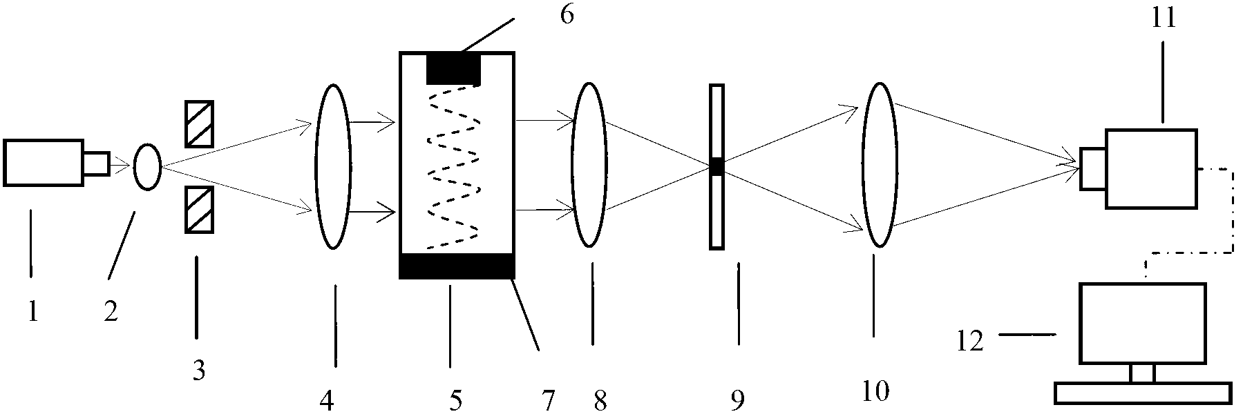
[0085] The device provided in this embodiment is used to measure the wavelength of ultrasonic waves. Such as figure 1 As shown, it includes a light source 1, a beam expander lens 2, a diaphragm 3, a collimating lens 4, a transparent water tank 5, an ultrasonic transducer 6, a sound-absorbing medium 7, a lens 8, an amplitude filter 9, an imaging lens 10, and a surface array Photodetector 11 and computer 12; light source 1, beam expander lens 2, diaphragm 3, collimating lens 4, transparent water tank 5, lens 8, amplitude filter 9, imaging lens 10 and area array photodetector 11 along the beam The advancing direction is arranged in sequence, the ultrasonic transducer 6 and the sound-absorbing medium 7 are respectively located on the two sides of the transparent water tank 5 parallel to the light beam, and the area array photodetector 11 is connected to the computer 12. Among them, the light source 1 can be a monochromatic light source or an ordinary low-power laser, such as a mer...

Embodiment 2

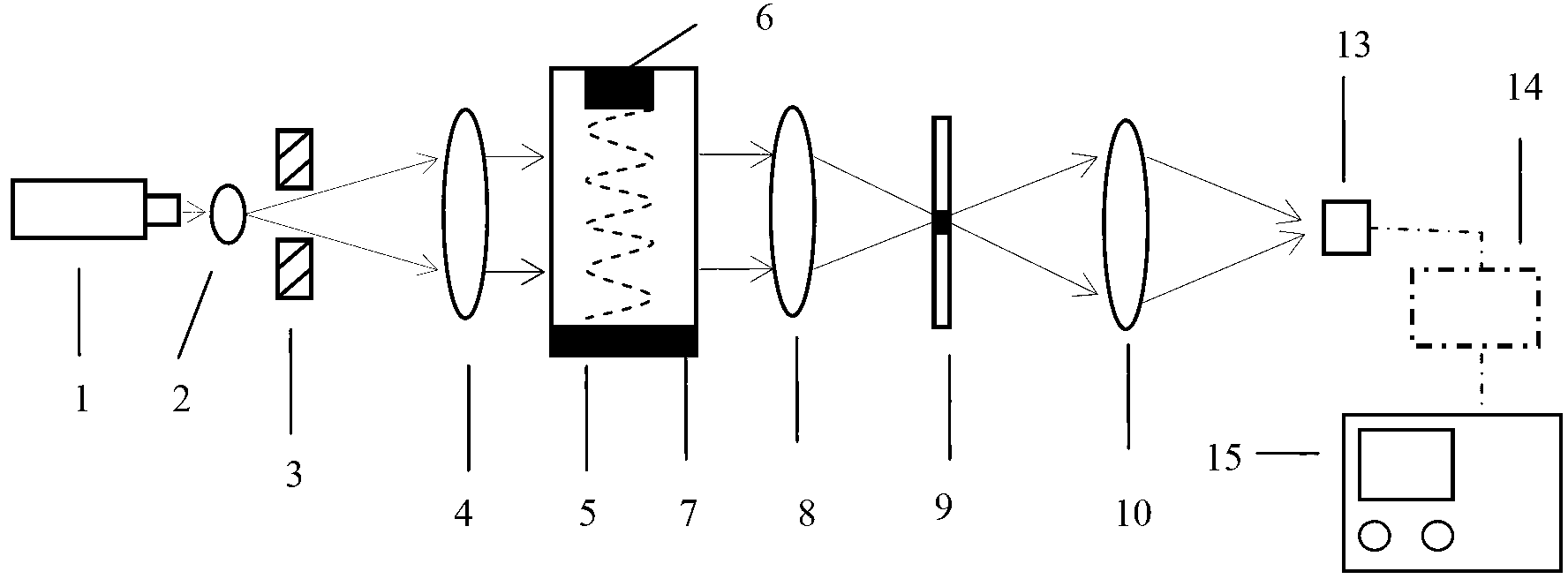
[0092] This embodiment is used to measure the wavelength and frequency of ultrasonic waves. Use as figure 2 The device shown includes a light source 1, a beam expander lens 2, a diaphragm 3, a collimating lens 4, a transparent water tank 5, an ultrasonic transducer 6, a sound-absorbing medium 7, a lens 8, an amplitude filter 9, and an imaging lens 10. Photodetector 13 with small holes (photodetector with small holes with sufficiently large response frequency), amplifier circuit 14 and oscilloscope 15; light source 1, beam expander lens 2, diaphragm 3, collimator lens 4, transparent The water tank 5, the lens 8, the amplitude filter 9, the imaging lens 10, and the photodetector 13 with small holes are arranged in sequence along the forward direction of the beam. The photodetector 13 with small holes is placed on the measuring fine-tuning seat. The photodetector 13, the amplifying circuit 14 and the oscilloscope 15 are connected in sequence, and the ultrasonic transducer 6 and t...

Embodiment 3

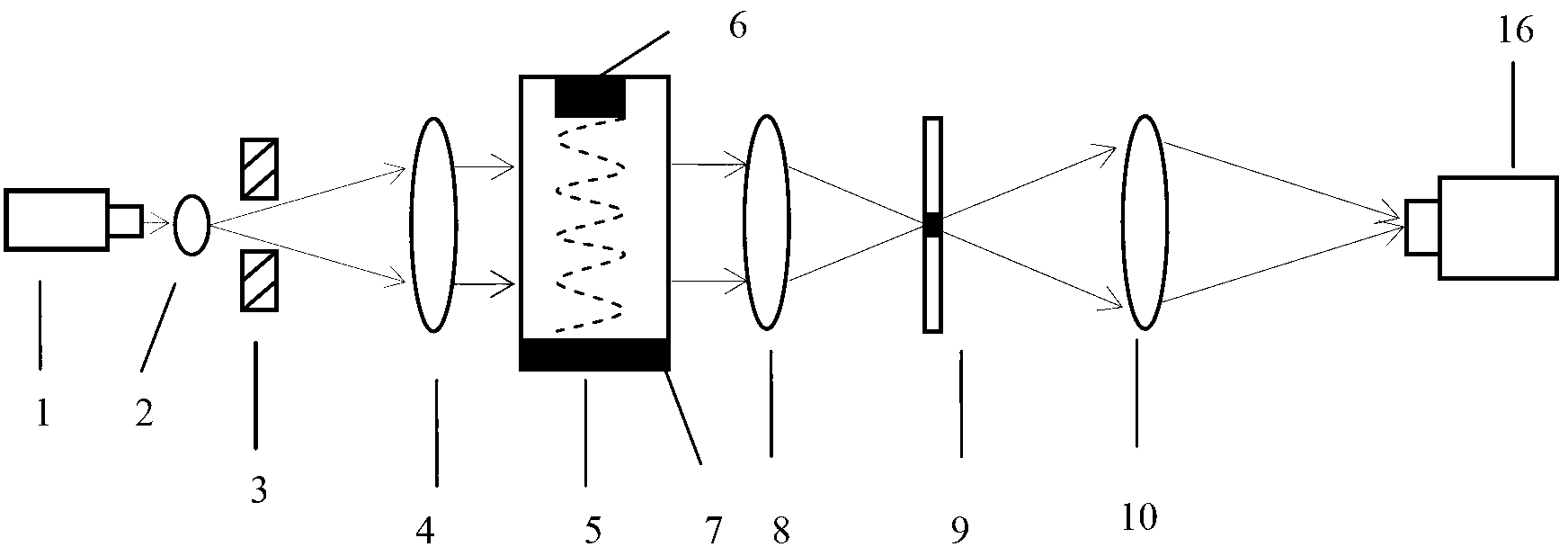
[0098] The device provided in this embodiment can be used to measure the wavelength of ultrasonic waves. The components and the arrangement of the components are roughly the same as the device provided in Embodiment 1, except that the computer 12 is not included and the micrometer eyepiece 16 is used instead of the area array photodetector 11. The light source 1 can be a monochromatic light source or an ordinary low-power laser, such as a mercury lamp, a sodium lamp, a helium-neon laser, a semiconductor laser diode, etc., and the light beam emitted by it passes through the beam expander 2, the diaphragm 3, and the collimator 4 to output a uniform The parallel light is projected on the traveling wave ultrasonic grating generated by the ultrasonic transducer 6 and the sound-absorbing medium 7, and the frequency spectrum of the ultrasonic grating is formed by the lens 8. After the frequency spectrum is processed by the amplitude filter 9, the spectral image of the grating is obtain...


PUM

PropertyMeasurementUnit
Diameteraaaaaaaaaa
Diameteraaaaaaaaaa

Abstract

The invention discloses a method and a device for measuring the speed and frequency of ultrasonic traveling wave in a liquid. The method comprises the following steps that a monochromatic parallel light beam is vertical to an ultrasonic transmission direction and radiates a dynamic ultrasonic grating that the ultrasonic wave forms in the liquid; the dynamic ultrasonic grating penetrates through a lens and the diffraction spectrum of a traveling wave ultrasonic phase grating is formed; the spectrum is processed and imaged through an amplitude filter and an imaging lens, and a spectrum image of the ultrasonic traveling wave grating is obtained; the spacing of two adjacent spectral lines on the spectrum image is measured, and the wavelength of the ultrasonic wave in the liquid is calculated; the change of an electrical signal after the previous level of spectrum and zero level spectrum of the spectrum image are mixed is detected or recorded, and the frequency of the ultrasonic wave is worked out; the speed of the ultrasonic wave in the liquid is worked out through the wavelength and the frequency. The device for realizing the method comprises a light source, a transparent sink, a lens I, the amplitude filter, the imaging lens and the measuring device which are sequentially connected, and a sound-absorbing medium and the ultrasonic transducer are arranged in the transparent sink and are respectively arranged on both sides.

Description

Technical field [0001] The invention belongs to the technical field of optical measurement and metrology, and particularly relates to a method and device for measuring the velocity and frequency of ultrasonic traveling waves in liquid. Background technique [0002] The accurate measurement of the propagation velocity of sound waves or ultrasonic waves in liquids is of practical significance, and has important applications in the fields of sonar detection and positioning and liquid characteristics measurement. At present, the methods for measuring the speed of sound in liquids mainly include standing wave method, phase method, ultrasonic grating method and so on. The standing wave method and the phase method require the adjustment and movement of the device, and the measurement speed is slow, causing disturbance to the liquid and easily causing measurement errors, so the ultrasonic grating method is the most widely used. Ultrasonic grating measurement methods are generally divide...

Claims


Application Information

Patent Timeline
IPC IPC(8): G01H5/00G01H9/00
Inventor 黄佐华潘美妍梁婕曾映智吴泳波
Owner SOUTH CHINA NORMAL UNIVERSITY
Why Eureka
Try Eureka