
Workpiece platform system of photoetching machine

A technology of workpiece table and lithography machine, which is applied in microlithography exposure equipment, photolithography process exposure device, etc., can solve the problems of increasing the measurement error of the workpiece table displacement, the measurement is easily disturbed, and the optical structure is complex.

Active Publication Date: 2013-09-18
TSINGHUA UNIV +1
View PDF10 Cites 15 Cited by
  • Summary
  • Abstract
  • Description
  • Claims
  • Application Information

AI Technical Summary

Problems solved by technology

U.S. Patent Publication No. US2010 / 0321665A1 (published on December 23, 2010) discloses a grating reading head structure that can cooperate with planar grating measurement. Although this structure can measure vertical displacement, the reading head uses the principle of homodyne measurement , there are disadvantages such as the measurement is susceptible to interference and the signal is difficult to process, and it is difficult to achieve high measurement accuracy
Chinese patent documents (Application No.: 201210449244.9, 201210448734.7) respectively disclose a heterodyne grating interferometer measurement system. The reading head structure of the two interferometer measurement systems uses a quarter-wave plate to change the polarization of the beam state, the optical structure is complex, and the non-ideality of the optical components will lead to measurement errors, which will increase the measurement error of using the grating interferometer to measure the displacement of the workpiece table; both interferometer measurement systems can only measure two degrees of freedom Displacement, which will increase the number of interferometers arranged on the wafer stage, increase the difficulty of calculating the displacement of the workpiece stage, and reduce the measurement accuracy of the displacement of the workpiece stage

Method used


Image

  • Workpiece platform system of photoetching machine
  • Workpiece platform system of photoetching machine
  • Workpiece platform system of photoetching machine

Examples


Embodiment Construction

[0024] The structure, principle and specific implementation of the present invention will be further described in detail below in conjunction with the accompanying drawings.

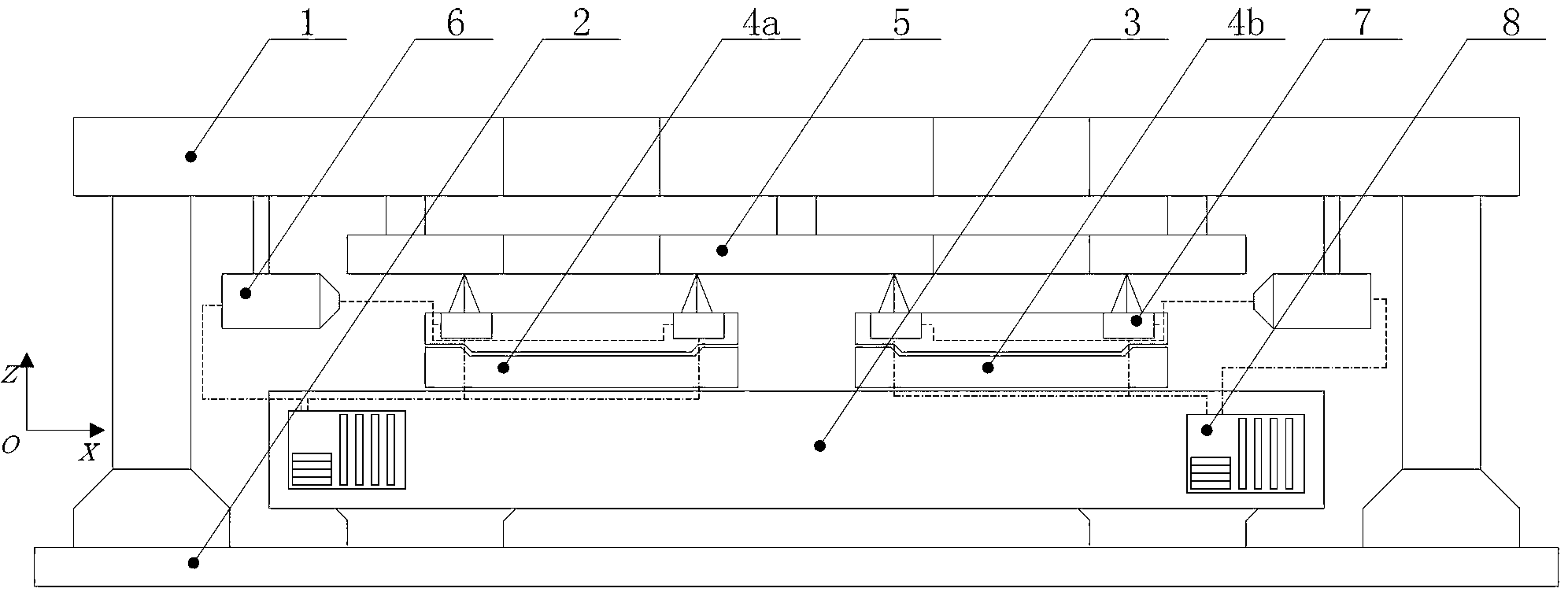
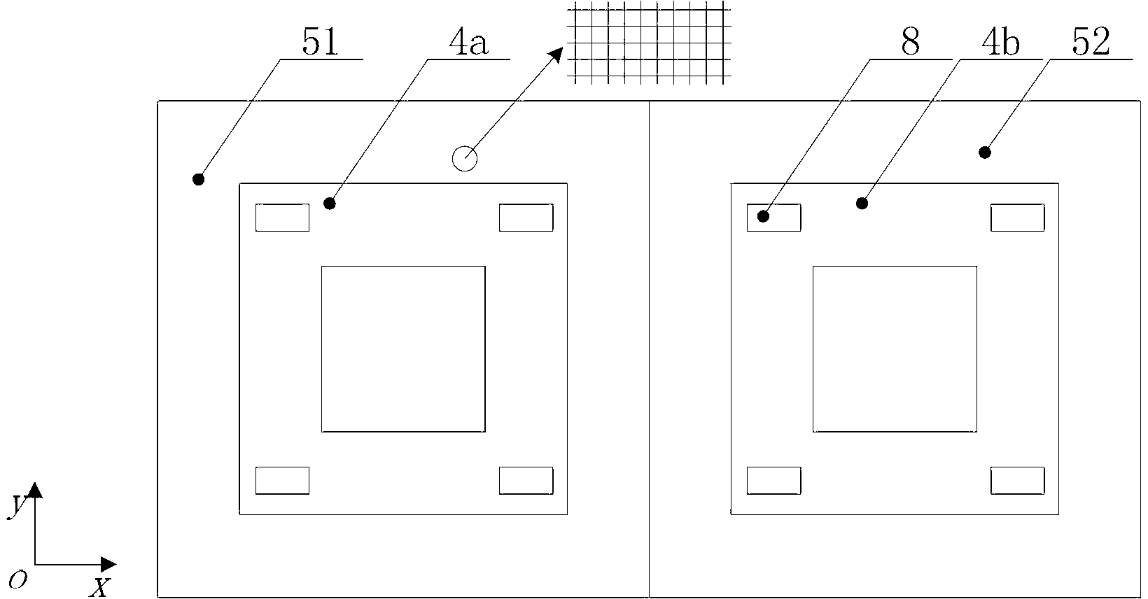
[0025] Please refer to figure 1 and 2 , figure 1 It is a schematic diagram of a lithography machine workpiece table system in the present invention, figure 2 It is a schematic diagram of the relative position of the measurement grating and the silicon wafer stage in the xoy plane of the present invention, combined with figure 1 and figure 2 The lithography machine workpiece platform system of the present invention is described. like figure 1 As shown, the photolithography machine workpiece table system includes a frame 1, a base table 3, a wafer table 4a running on an exposure station, and a silicon wafer table 4b running on a pretreatment station; the workpiece table system also includes a measuring grating 5, A dual-frequency laser 6, a three-degree-of-freedom heterodyne grating interferometer ...


PUM


Abstract

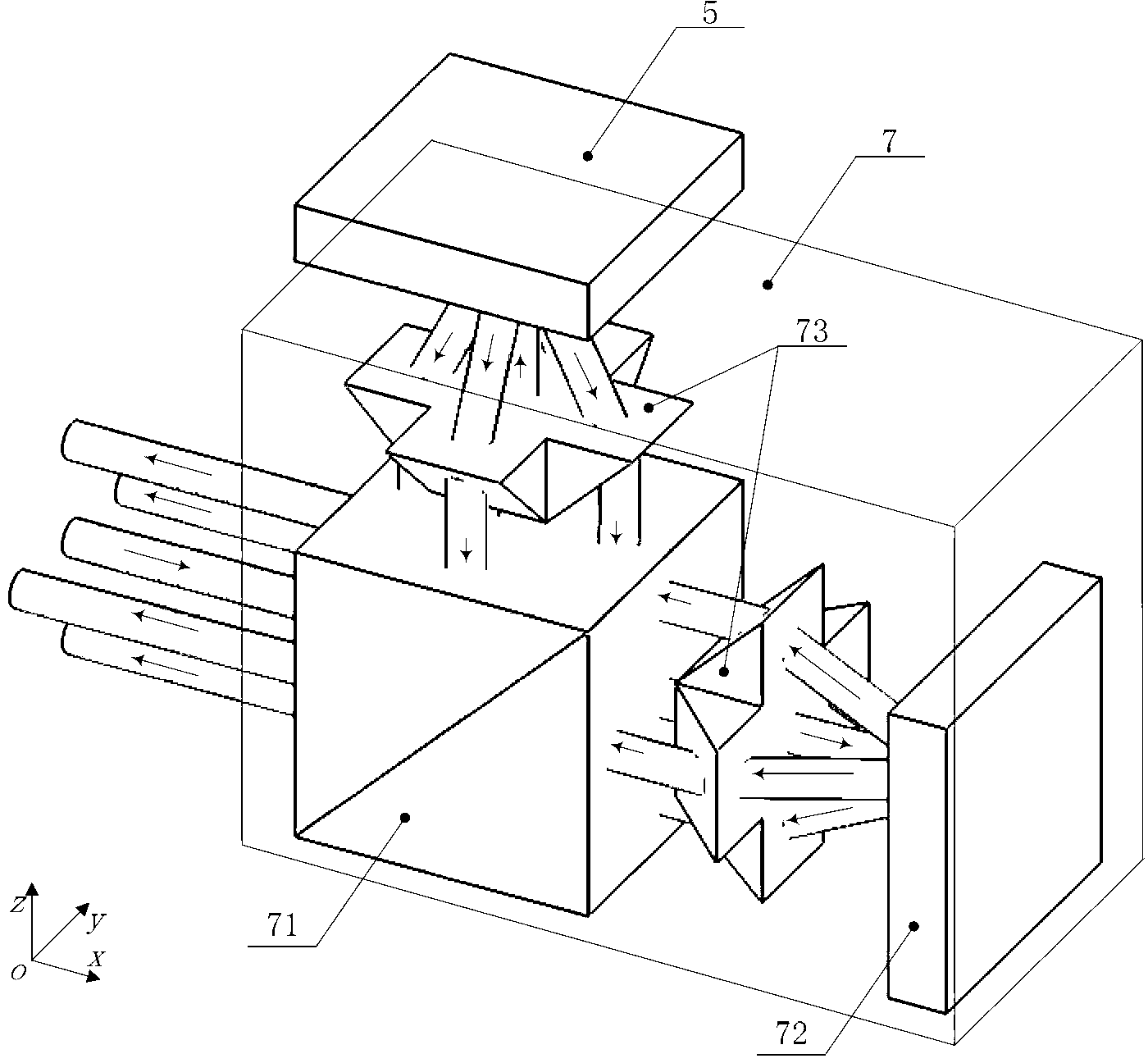
The invention discloses a workpiece platform system of a photoetching machine. The workpiece platform system comprises a rack, a base platform, two silicon-chip platforms, a measuring grating, a dual-frequency laser, three-freedom-degree heterodyne grating interferometers and a signal receiving and processing part, wherein the two silicon-chip platforms operate at an exposure station and a preprocessing station; the four corners of each silicon-chip platform are provided with one three-freedom-degree heterodyne grating interferometer respectively, and the measuring grating is arranged on the rack above the silicon-chip platform. Dual-frequency orthogonal-polarization laser emitted by the dual-frequency laser is transmitted to the three-freedom-degree heterodyne grating interferometers and the measuring grating by optical fiber, four beams of diffraction light of the measuring grating irradiate back to the three-freedom-degree heterodyne grating interferometers, and finally the four beams of measuring light signals are emitted to the signal receiving and processing part. When the silicon-chip platforms move relatively to the measuring grating, the reading in the signal receiving and processing part is utilized for acquiring six-freedom displacement of the silicon-chip platforms by calculation. The workpiece platform system disclosed by the invention has the advantages that the indexes such as measuring accuracy and dynamic performance of the silicon-chip platforms can be improved, and further the whole performance of the workpiece platform system is further improved.

Description

technical field [0001] The invention relates to a workpiece table system of a photolithography machine, in particular to a workpiece table system of a photolithography machine which uses a three-degree-of-freedom heterodyne grating interferometer to measure the displacement of a silicon wafer table. Background technique [0002] The lithography machine in semiconductor manufacturing equipment is the key equipment in the production of semiconductor chips. The ultra-precision workpiece table system is the core subsystem of the lithography machine, which is used to carry the mask plate and silicon wafer to complete the high-speed ultra-precision step-and-scan movement. The ultra-precision workpiece table system has become the most representative type of ultra-precision motion system due to its high-speed, high-acceleration, large-stroke, ultra-precision, and multi-degree-of-freedom motion characteristics. In order to realize the above-mentioned movement, the ultra-precision wo...

Claims


Application Information

Patent Timeline
IPC IPC(8): G03F7/20
Inventor 朱煜王磊杰张鸣刘召成荣杨开明徐登峰叶伟楠田丽张利秦慧超张金穆海华尹文生胡金春赵彦坡
Owner TSINGHUA UNIV
Learn More