Electrostatic generator, manufacturing method thereof and self-driven sensing system
A generator and electrostatic technology, applied in the direction of electrostatic generator/motor, generator/motor, electrical components, etc., can solve the problem of insufficient contact between two plates, increase the effective contact area, increase the surface charge density, and improve The effect of charge density
- Summary
- Abstract
- Description
- Claims
- Application Information
AI Technical Summary
Problems solved by technology
Method used
Image
Examples
Embodiment 1
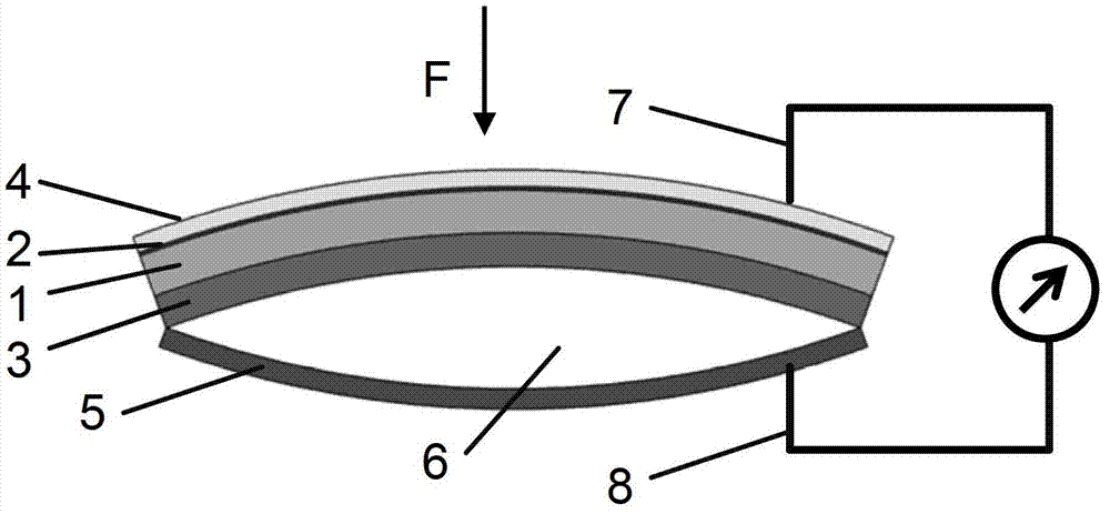
[0057] see figure 1 , the electrostatic generator in this embodiment includes: the curved flexible substrate includes an organic substrate 1 and a bending dynamic layer 2, and the organic substrate 1 forms an arched bend under the action of the bending dynamic layer 2, and the outer surface of the substrate ( Convex surface) prepared with an electrode layer 4, a polymer film layer 3 attached to the inner surface of the substrate (depressed surface), and a metal film 5 pasted on the edge of the polymer film layer 3, preferably a metal film 5 The area is equivalent to the area of the polymer film 3, that is, the area is basically the same. After the edge of the metal film 5 is pasted with the edge of the polymer film 3, an arched cavity is formed between the metal film 5 and the polymer film 3 6. The distance between the edge of the metal film 5 and the polymer film 3 is small, and the distance between the center is relatively large; wherein, the polymer film layer 3 and the m...
Embodiment 2
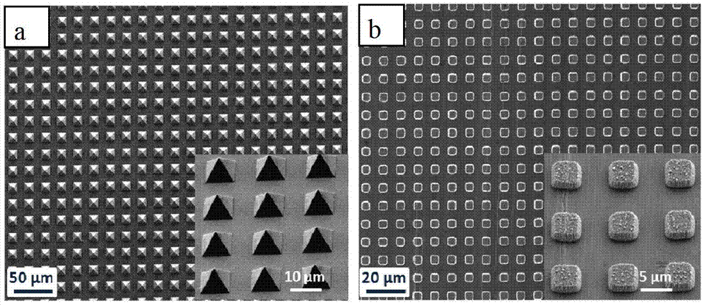
[0065] The difference between this embodiment and Embodiment 1 is that micro-nanostructures are formed on the surface of the polymer film layer and / or metal film forming the arched cavity, and the micro-nanostructure faces the surface formed by the polymer film layer and the metal film. The cavity can effectively increase the contact area of the polymer film layer and the metal film layer when they are in contact with each other under the action of external force. The micro-nano structure can be prepared on the opposite surfaces of the polymer film layer or the metal film, and the micro-nano structure can only be prepared on the surface of one film. This nanostructure can be a linear, cubic, or quadrangular pyramid-shaped array prepared by methods such as photolithography. The size of each such unit in the array is on the order of nanometers to micrometers. The shape should not limit the scope of the invention.
[0066] Taking the method of forming micro-nano structures on ...
Embodiment 3
[0072] Introduce the preparation method of the electrostatic generator of the present invention in this embodiment, see Figure 5 As shown in the flowchart, the preparation method of the electrostatic generator includes:
[0073] Step S1, providing a curved flexible substrate;
[0074] Step S2, attaching the polymer film to the inner surface of the substrate;
[0075] Step S3, preparing an electrode layer on the outer surface of the substrate;
[0076] Step S4, using insulating glue to glue the edge of the polymer film to the edge of the metal film, so that an arched cavity is formed between the polymer film and the metal film.
[0077] The flexible substrate can be a single-layer flexible material, such as curved silicone, or a double-layer composite substrate. For two-layer composite substrates, curved flexible substrates are available, including:
[0078] Step S11, providing a planar organic substrate;
[0079] Step S12, using a high-temperature deposition method to pr...
PUM
| Property | Measurement | Unit |
|---|---|---|
| Thickness | aaaaa | aaaaa |
Abstract
Description
Claims
Application Information
 - R&D
- Intellectual Property
- Life Sciences
- Materials
- Tech Scout
- Unparalleled Data Quality
- Higher Quality Content
- 60% Fewer Hallucinations
Browse by: Latest US Patents, China's latest patents, Technical Efficacy Thesaurus, Application Domain, Technology Topic, Popular Technical Reports.
© 2025 PatSnap. All rights reserved.Legal|Privacy policy|Modern Slavery Act Transparency Statement|Sitemap|About US| Contact US: help@patsnap.com


